Top image artwork by Noel Sickles for Rocket to the Moon, LIFE magazine January 17, 1949. Lower left artwork by Louis S. Glanzman for On The Trail of the Space Pirates by Cary Rockwell 1953, a Tom Corbett Space Cadet book. Lower right from Space Race card game from Ed-U-Games, 1969. As you can see, artists of that era tended to "borrow" a lot.
How Big Is It?
Typical breakdown of the dry mass of a spacecraft (total mass less the propellant mass). For "payload" read "everything else". From NASA Space Power and Energy Storage Roadmap
The Polaris is 792.6 tons of propellant and 396.3 tons of everything else. How big is this, exactly?
When comparing the spacecraft to other vehicles, just use the "everything else" value, ignore the propellant mass. This is because few earthly vehicles have total masses dominated by fuel mass as much as rockets are. How does 396.3 tons stack up?
Rick Robinson notes that is pretty small compared to "wet-navy" vessels. It's under the size of a coastal corvette. But compared to aircraft, it's huge. A Boeing 747 is only 180 tons empty. If you want to get an idea of other sizes, go check out Jeff Russell's huge Starship Dimensions website and Florian Käferböck's impressive
Rockets and Space Ships Size Comparison.
Note: according to the blueprints the Michael Battleship (49) is 408 feet tall. However, this would make the Shuttle Orbiters mounted on the battleship too small. I scaled the blueprint so the Orbiters were at their official length, which made the Michael 433 feet tall.
Credits for the computer meshes used in the images below:
Green is NFL standard football field. Beige thing is an Ogre Mark V Click for larger image
Click for larger image
Click for larger image
Click for larger image
Click for larger image
Click for larger image
Click for larger image
Click for larger image
Click for larger image
Click for larger image
Click for larger image
Click for larger image
Click for larger image
Click for larger image
Click for larger image
Click for larger image
Click for larger image
Click for larger image
Calculating Volume and Mass
The Easy Way 1
If you just want something really quick and dirty:
Estimate somehow the volume (m3) of your spacecraft. Calculate the mass by multiplying the volume by the average density (kg/m3) of a spacecraft.
Estimating Volume
There are equations to calculate the volume of simple geometric objects such as cubes, spheres, cylinders, and cones. Approximate the spacecraft as an assemblage of such objects, calculate the volumes, then add them all up. Example:here.
See if somebody else has already calculated the volume. Example: According to ST-v-SW.Net the internal volume of the TOS Starship Enterprise is 211,248 cubic meters.
Use the known volume of a comparable existing object. Example: a Russian Oscar submarine has a volume of 15,400 cubic meters. It is a good size for a spaceship.
If the spacecraft is approximately a sphere or approximately a cylinder, just use the ship's average radius and height to calculate an approximate volume using the sphere or cylinder volume formulae. Close enough for government work.
Make it up out of your imagination.
Of course there is some differences of opinion on the exact value of the average density of a spacecraft.
One easy figure I've seen in various SF role playing games is a density of 0.1 to 0.2 metric tons per cubic meter (100 to 200 kilograms). That corresponds to average pressure compartments being cubes 10 meters on a side, with pressure bulkheads averaging 17 to 33 kg/m2.
Ken Burnside did some research when he designed his game Attack Vector: Tactical. He found that jet airliners have an average density of about 0.28 metric tons per cubic meter, fighter aircraft 0.35 tons/m3, wet navy warships from 0.5 to 0.6 tons/m3, WWII battleships 0.7 tons/m3(it don't take much excess mass to send them straight to Davy Jones locker), and submarines 0.9 tons/m3. For the combat spacecraft in AV:T, Ken chose a density of 0.25 tons/m3.
Ship Densities
Ship
Density
Attack Vector: Tactical
0.25 ton/m3
Jet Airliners
0.28 ton/m3
Fighter Aircraft
0.35 ton/m3
Wet Navy Warships
0.5 to 0.6 ton/m3
WWII Battleships
0.7 ton/m3
Submarines
0.9 ton/m3
A student of the game Orbiter (who goes by the handle T. Neo) used the 3D models in the game to figure the volume of various space constructions. Dividing by their known masses yielded the densities.
* Large portion of volume is dedicated to propellant
Fans of the Traveller role playing game have to do a bit of work. Starships in Traveller are rated in terms of "displacement tons" or "dtons". This is a measure of volume, not mass. 1 dton is 14 cubic meters, which is approximately the volume taken up by one metric ton of liquid hydrogen (actually closer to 14.12 m3). Liquid hydrogen is starship fusion fuel.
So if you assume a Traveller starship has an average density of 0.2 tonnes/m3, then given dtons the starship mass in metric tons is:
starshipMass = dtons * 14 * 0.2
where:
starshipMass = mass of starship (metric tons)
dtons = displacement of starship (displacement tons or dtons)
0.2 = average density of starships (tonnes/m3)
Example: a Broadsword class mercenary cruiser has a volume of 800 dtons (or 1200 depending on where you read it). This means its mass is 800 * 14 * 0.2 = 2,230 metric tons.
Traveller deck plans are confusing as well. If they are ruled off in a square grid, chances are the squares are 1.5 meters on a side. The space between the floor and the ceiling of a deck is assumed to be 3 meters. Bottom line is that on a Traveller deck plan 1 dton is represented by two grid squares.
Typical breakdown of the dry mass of a spacecraft (total mass less the propellant mass). For "payload" read "everything else". From NASA Space Power and Energy Storage Roadmap
The second quick and dirty method:
Estimate the mass (kg) of each major component. Divide the mass of each major component by its density (kg/m3) to find the volume of each major component. Total the masses to get the spacecraft mass, total the volume to get the spacecraft volume.
Estimating Mass
Often you have the total mass, and the propellant mass. The dry mass is the total mass less the propellant.
If you have the mass ratio, you can figure your dry mass by totaling up the various components, then use the mass ratio to calculate the propellant mass and total mass.
remember that average NASA spacecraft dry mass (i.e., sans propellant) divides up to include:
Percentage of Dry Mass
System
Percentage
Structure
21.7%
Power Systems
28.0%
Propulsion
3.7%
Thermal (heat radiators)
3.4%
Communication
7.5%
Guidance, Navigation, and Control
8.0%
Everything Else
26.7%
Keep in mind that this is for NASA style spacecraft. The percentages for, say, the Starship Enterprise will be totally different and anybody's guess.
Now all you need are some figures on the average density of these various items and you can calculate quick and dirty ship volumes. I'm looking into it but it's hard.
Lucky you, Eric Rozier has implemented the algorithm below as an on-line calculator.
Assumptions: as a first approximation, the spacecraft is modeled as a free standing column resting upon the engines. The column is "thin-walled", that is, the column radius divided by the hull thickness is less than 0.1. The column is only supported by its walls (monocoque construction). The column has its mass uniformly distributed along its length. The ratio of column's length to its diameter is 3.2 : 1.0. The hull is assumed to be capable of withstanding forces equal to its mass times gs of acceleration on any axis: axial, lateral, or bending.
This means that the following formula only work for a cigar-shaped rocket, not a spherical one.
Decide upon the volume, or total displacement of the hull in cubic meters (m3). This will boil down to volume for reaction mass plus volume for the crew and cargo. Calculate the volume for your reaction mass by
Vpt = Mpt / Dpt
where
Mpt = mass of propellant (kg)
Dpt = density of propellant (kg/m3) = 71 for liquid hydrogen, 423 for methane, 682 for ammonia, and 1000 for water
Vpt = volume of propellant (m3)
If you don't know the mass of the propellant, it can be calculated from the dry mass and the mass ratio:
Mpt = (R * Me) - Me
where
R = mass ratio (dimensionless number)
Mpt = mass of propellant (kg)
Me = mass of rocket with empty propellant tanks (kg)
Add the volume of the reaction mass to the desired living space volume to get the spacecraft's volume. Later you can figure the approximate spacecraft dimensions by using the formula for the volume of a cylinder ( v = π r 2h ), keeping in mind that it should be about 3.2 times as high as it is wide (although you can get away with larger values).
Now comes the fun part. This is going to be what they call an "iterative process". This means you do the calculations, take the results and do the calculations again on the results.
Step 1: Find Mass
M = M~st + Mst
where
M = mass of spacecraft (kg)
M~st = sum of mass of all spacecraft components except structure (kg)
Mst = spacecraft's structural mass (kg)
Since this is an iterative process to calculate Mst, the first time through Mst will be equal to zero.
Step 2: Find Density
D = (M/1000) / V
where
D = density of spacecraft (ton/m3)
M = mass of spacecraft (kg)
V = volume of spacecraft (m3)
Note that here density is in tons, not kilograms per cubic meter
Step 3: Find Structural Support Volume
Vsr = (V4/3 * Apg0 * D) / (1000 * Thm)
where
Vsr = volume of structural mass needed to support spacecraft (m3)
V = volume of spacecraft (m3)
Apg0 = maximum acceleration of spacecraft (Terra gs)
D = density of spacecraft (ton/m3)
Thm = "toughness" of hull material. Hard steel = 2.86.
Step 4: Find Anti-Buckling Structural Volume
Vsb = (V1.15 * (Apg0 * D)0.453) / 300
where
Vsb = volume of structural mass needed avoid buckling (m3)
Step 5: Find Actual Volume
The actual volume Vs is equal to the larger of Vsr and Vsb.
(Note: Mr. Thrash informs me that an aeronautical engineer of his acquaintance is of the opinion that while the equation in step 4 works fine for a small rocket with a ten ton payload, the equation does not scale well if used for a larger rocket. The engineer is sure that Vsr will almost always be enough to resist buckling as well. In other words, just use Vsb = Vsr).
Step 6: Find Structural Mass
Mst = Vs * Dhm
where
Mst = spacecraft's structural mass (kg)
Vs = volume of structural mass (m3)
Dhm = density of hull material (kg/m3) (7,850 for steel, 4,507 for titanium, 1,738 for magnesium)
Step 7: Start Over from Step 1
Use the new value for Mst and start over. Repeat until the value for Mst stops changing (or you get tired).
When you have your final value for Mst, and M, use M to check and see if the spacecraft's mass ratio is still acceptable. If not, reduce the value for M~st and do some more iterations.
Now you know why rocket scientists use computers to do all the grunt work.
Remember that the mass of the propellant tanks will be approximately equal to full propellant mass times 0.15. The tank mass will be included in the structural mass, if the ship designer is not totally incompetent.
The shortcut is to stop at step seven, reduce M~st by Mst, and everything will add up.
Calculating Volume Of Existing Model
Russian Typhoon submarine, about 20 meters longer than an Oscar-II.
Figuring the hull volume of an existing design is a bit more tricky.
By way of example, a Russian Oscar-II submarine is an oval cylinder about 18 meters wide by 9 meters tall by 154 meters long. It has an internal volume of about 15,400 cubic meters. It has a density of about 0.9 metric tons per cubic meter, so it has a mass of about 15,400 x 0.9 = 13,900 metric tons.
There are equations for calculating the internal volume of various geometric shapes. What you have to do is approximate your spacecraft design using only these shapes. A sphere is easy. A classic cigar shape is sort of a cylinder with a cone on each end. You'll find a crude example of that here.
If your spacecraft is a complicated shape like the Starship Enterprise, you have a real problem.
If you have a physical model of your spacecraft, you can try estimating its displacement by caulking it water-tight, immersing it in a container of water, and measuring the water it displaces. Alternatively, fill a box with sand, dump the sand into measuring cups to measure the volume of sand, put the model in the box and fill it with sand, dump the sand out into measuring cups, and finally subtract the two volumes to discover the volume of the model.
The following tips are specific to the Blender software, but an artist skilled with another 3D computer modeling program could adapt the tips to their software. Myn.pheos is a native of Slovakia, and English is his second language. Myn.pheos:
Area and Volume
Guessing the volume of spacecraft isn't accurate in most cases. Boxy shapes aren't the most pleasing, and computing volume or area of curved surface by hand is tedious and hard. So the best approach is to let the computer [do the] work for you. In Blender, there is no build-in way to compute volume of objects. But there exist scripts than can do this. One of the is Quantities Bill by Yorik. It computes length, area or volume depending on the topology of mesh. If you have the shape of the spacecraft in your mind, let it pass the test. Roughly model the hull, propellant tank or crew compartment (it must be one object, with no holes in it) so you can get the volume. If you want to know the area of hull, simply remove the smallest face from the mesh and run the script. The figures aren't exact (this depends on how precisely you modelled the hull), but they are obtained fast, and it's easy to [re-calculate the figures if you alter the shape of the hull].
Where is the Center of Gravity?
This is easy to guess in case of homogeneous objects. But spaceships aren't that case. When you know the mass of spacecraft, rough location of components and their estimated weight, you can try to search for the center of gravity (COG). In Blender, it is possible to find the COG easily, just place vertexes in COG of each component. Decide the weight of each vertex, and then add as many as you'll need. Logically, the sum of them should be equal to total mass of ship. To get the COG, simply select all vertexes and make sure the pivot is set to Median point.
(ed note: in Blender, if the pivot control is set to "Median", when you select a group of vertexes the pivot control will automatically appear at the mathematical median point. Myn.pheos is saying that at the center of gravity of each component, place a number of vertexes proportional to that component's relative mass. Select all the COG vertexes of all the components, and the pivot control will indicate the COG of the spaceship as a whole. Keep in mind that the ship's axis of thrust must pass through the COG)
Where to place radiators?
That depends on the shape of the ship. If you have several spots where they look good, you can test the placement. This involves rendering the image and then using histogram to interpret the rendered result. First create two materials. For hull, create fully transparent material (Alpha = 0.0), with no specularity (Spec=0.0), don't forget to check the Ztransp button on. For radiator, use total white material (Col = R 1.00, G 1.00, B 1.00), with again without specularity (Spec=0). Make sure both receive all ambient colour (Amb = 1.0). Now to the environment settings. As background, use total black color (HoR = 0.0, HoG = 0.0, HoB = 0.0, ZoR = 0.0, ZoG = 0.0, ZoB = 0.0), and ambient perfect white (AoR = 1.0, AoG = 1.0, AoB = 1.0). Turn on Ambient Occlusion, make the Sub button pushed (so it darkens occluded spots), ensure that Energy is 1.0 and Plain button pushed.
Now only to set the camera (the best to be perpendicular to the radiator) and render.
Open the rendered image in an image editor. I use GIMP, but only the histogram is important. Now set the lower value in histogram to the lowest non-zero number (remember the pitch black background?), and read the statistical data. The most important is Mean value, this is the average value of all pixels on radiator. Divide this number by 255 to get the percentage of unoccluded area. There rest is probably heating up the ship, so change try with another radiator position.
This method has some weak points, but it is good enough for some decisions. The fully occluded pixels aren't taken into account, the precision increases with samples, the edges aren't treated well (they are not full white, if antialiasing is on).
Myn.pheos
I must say that I am very impressed with Myn.pheos' technique. I am reasonably skilled with Blender, but it never occurred to me that it could be used to find centers of gravity and optimal heat radiator placement. Myn.pheos is a genius.
Dogmatic Pyrrhonist
After shadow shields were brought up in William Black's feed regarding his work on a Gas Core Rocket, I had a good read about various things (mostly from Winchell Chung's Atomic Rocket pages, see http://www.projectrho.com/public_html/rocket/radiation.php).
Turns out my prior plan of wide-short expanding radiator panels would result in radiation scattering, eventual enbrittlement of the radiators, and basically cooking the crew with neutrons, and gamma rays. The radiator free, high thrust, low ISP edition had no such issue, and has a simple shadow shield in line now. But the high ISP needed a radiator rethink.
I have a plan for the radiators, much like one of the pre-movie sketches of the Martian's Hermes on Atomic Rockets (http://francisdrakex.deviantart.com/art/Hermes-from-The-Martian-rear-view-485084228). Basically a triangle type arrangement made from staggered rectangular panels that all fold away.
That means a much longer frame to hold all that radiator. All of it, forward of the shadow shield.
Anyway, WIP, this is the rocket, edition one of the shadow shield, and the frame structure. I'll be adding a final frame at the end to spread load onto a wider area. I'll be wanting that as a separate piece, as the KSP heat transfer systems don't include cooling fluid pumping, so the frame, rocket and radiators will all have extremely heat conductive values to mimic the working fluid. Which means I'll need one extra piece to be an insulator, to protect the rest of the craft from those 1390C radiators.
William Black
This is looking great! I recall we had that conversation early on, when I described why the rectangular radiators arrayed around the nozzle would reflect radiation forward onto crew and vehicle, and so would definitely need to be forward of a radiation shadow shield, or did I have that discussion with Winchell Chung? The propulsion bus for my version is definitely an in-space assembly. I gathered (from yours or Winchell Chung's comments) that for KSP purposes it would need to be segmented and fold-away.
Oh, BTW, data sheet for 5% Borated Polyethylene here http://www.deqtech.com/Shieldwerx/Products/swx201hd.htm
Dogmatic Pyrrhonist
William Black Yep, I remember all the reasons why you'd gone for the triangular shape. At first I was going to just dismiss the idea under the category of "Kerbals don't care". But then, I thought, I'd still like the thing to be real-world-sane, esp as I'm looking at doing some Realism-Overhaul conversions for some of the mods. So, while there's no mechanism in game to handle it, I have come around to thinking it should be arranged to at least mostly shield payload/crew.
I roughed in a truncated triangle to get the surface area right for the radiators, and adjusted the shadow shield to match. I might need more than 51.5m of frame. :-/
That's quite the shadow shield.
click for larger image
William Black
Dogmatic Pyrrhonist, yeah, that's pretty much how I did it. I needed a 6.7 meter diameter shadow shield and wound up adding an additional 9.1 meters to my truss, two 3.0 meter sections between the shadow shield and the aft edge of the radiator and one 3.0 meter section between the forward edge and propellant tank. With the 29.8 by 10.01 meter propellant tanks for the 80 day Mars mission spacecraft that puts my crew module 12.4 meters past the 100 meter minimum separation between crew and nozzle.
(Then noted virtual production engineer Ron Fischer made a quiet but brilliant suggestion:)
Ron Fischer
You can use lighting and shadows in your CG rendering program to analyze the shadowing of the shield. In fact, this is where the original math for lighting simulation came from: radiation studies on tanks in the 60s. Might as well go "Back to the Future" on that one!
(You could almost see the light bulbs lighting up over each person's head.)
Dogmatic Pyrrhonist
Ron Fischer I had not thought of that.
Dogmatic Pyrrhonist
Dammit Winchell Chung , I've got enough tabs open in my browser already. :-)
Initial ray casting adjustments, although I haven't checked yet if that's enough radiator. Nor whether it's still in shadow when rotated 45 or 90 degrees.
click for larger image
Winchell Chung
Dogmatic Pyrrhonist You might have to simplify the model. First approximation with a light at the reaction chamber, the shadow shield, and the radiator.
If you want to get into actually modeling the scatter, be my guest.
Dogmatic Pyrrhonist
Winchell Chung Scatter is easy. Just place light sources at the outside edges of things that might scatter. I should disable rendering of things that would be basically transparent to neutrons or gammas, etc.
oooo.... transparency. :-)
Winchell Chung
Dogmatic Pyrrhonist Yes! That's the ticket! Radiation design by CGI mesh modeling. Hot stuff!
Ron Fischer
Very cool Dogmatic Pyrrhonist Also, Winchell Chung I recommend requesting use of those for Atomic Rockets! Should illustrate the point nicely!
Hey! I should suggest this to the good people making Kerbal. Could be a cool part of the design experience for nuclear spacecraft.
It is interesting to note that the cylinders which (I guess) are used to gimbal the engine get quite a strong dose.
William Black
Dogmatic Pyrrhonist and Winchell Chung I've found that you can optimize the shadow shield using this technique. I've found that a smaller shadow shield diameter is possible by adding truss segments between the shadow shield and the aft end of the radiator panels. Because the truss is lighter than the shadow shield, you realize a mass savings.
Meanwhile William Black was already hard at work on a GCR. He is also using Blender 3D.
Click for larger image, and to read William Black's detailed analysis and work logs on the project.
detail
When William Black read Ron Fischer's brilliant suggestion, he quote "found this to be a compelling proposition, an opportunity to test out the validity of my design" unquote.
click for larger image
I found this to be a compelling proposition, an opportunity to test out the validity of my design. Dogmatic Pyrrhonist and I both set about individually setting up a radiation simulation by CG lighting; his results are to be found at links in this thread November 6, 2015 Initially, for purposes of approximation, I used a cone, which you strip out of the scene once it has served its purpose, this is used to insure the radiators panels (and everything else forward of the shadow shield) are completely within the shadow region. It is a matter of placing the cone so to intersect the aft-most edge of the radiation shadow shield, if all components forward of the shadow shield are properly placed nothing should protrude through the surface of the cone. I realized the technique can be used not only to optimize the shadow shield in terms of placement, but also in terms of diameter. Previously, using the cone I had realized that increasing the distance between the aft edge of the radiator panels and shadow shield allows a smaller diameter shadow shield. Using this technique allowed me to test that theory, and it in fact worked exactly as anticipated. Truss segments mass less than the 5% Borated Polyethylene of the shadow shield, so there is a savings on structural mass, which is important because, as we all know, every gram counts. I rendered the scene against a gray background, then a second time against a completely black background. I made an attempt (which may be laughable) to model the plume. I used a bright blue emission shader. I was curious in regards to how much blue emission, representing radiation from the plume, would show up on the structure of the vehicle. Lacking data on the physical characteristics of plume expansion immediately after leaving the nozzle, this may be an insufficient test, so I’m not sure this adds anything, but darn, it looks nifty. Ron Fischer suggested I attempt this again with volumetric lighting, and I intend to do so at a future date.
Physicist Luke Campbell had some additional suggestions:
You might want to check for radiation scatter from the rocket bell to the radiators. You could make the entire structure aft of the shadow shield glow, make the shadow shield 100% black, make the spacecraft fore of the shadow shield white, and then look at the craft from the back to see if the edges of the radiators are illuminated. If they are, neutrons and gamma rays emitted from the reactor can scatter off the rocket bell (say), bypass the shadow shield, scatter off the radiator, and make their way to the payload/crew/control electronics/whatever. Just eyeballing it, it looks like that could happen. Also, from the linked post describing the design — you probably will want a few centimeters of lead fore of the borated polyethylene, for sopping up the gamma rays. The set of materials that are good at stopping neutrons seems to be orthogonal to the set of materials that are good at stopping gamma rays. By putting the poly between the reactor and the lead, you arrange it so that gamma rays produced by neutron interactions in the poly are also blocked by the lead part of the shield.
From Luke Campbell (2015)
click for larger image
click for larger image
click for larger image
Physicist Luke Campbell examined my Blender radiation simulation and suggested some modifications which might test the model more rigorously. Following his suggestion I applied emission shaders to everything on the “hot” side of the shadow shield, so, rather than just the gas core reactor, this now includes all structure (truss, engine gimbals and supports) and all LH2, Helium coolant lines, and turbine pumps and associated plumbing including the turbine exhaust, and of course the expansion nozzle. I applied a flat non-reflective black shader to the shadow shield, and applied a white shader to all structure on the “safe” side of the shadow shield (truss, radiator panels and heat exchanger housings, tensioning cable, cable rigging, LH2 and Helium coolant lines). Changes in place, I ran the radiation simulation again. As you can see from the top image the simulation revealed that radiation was in fact impinging on the aft outer corners of the radiator panels and the tensioning cables, a fact not visible in my previous simulation. This means radiation would travel along these parts of the vehicle, turning them into additional sources of radiation, damaging the radiator system and vehicle structure via radiation embrittlement, damaging control and electrical systems, and it means radiation would scatter from these points onto the rest of the vehicle posing a hazard to the crew. I added truss segments and increased the diameter of the radiation shadow shield, running the simulation after each configuration change, till I arrived at a good result, which you can see in the second image down. The lower two images are non-rendered screen captures of the same area of the model, the aft-most portion of the propulsion bus. Before structural modifications on the Left, and the final optimized configuration, on the Right.
Something like Myn.pheos technique for placing heat radiators was used to solve the mystery of the Pioneer Anomaly. The trajectory of space probes in general and the Pioneer probes in particular should follow precisely Newton's Laws of Motion. Once you've accounted for all the extra factors, of course. So scientists were quite upset when the probes started to gradually diverge from their calculated trajectory. There are all sorts of proposed explanations, ranging from observational errors to new laws of physics.
Dr. Frederico Francisco (Instituto Superior Técnico, Lisbon) and colleagues believe they have the answer. Others have tried and found wanting the hypothesis that heat radiated from the probes could be the culprit. But Dr. Francisco et al submit that this is because the radiation mathematical models are too simplistic. Using the 3D CGI rendering technique known as "Phong shading", they have shown this will account for the Pioneer Anomaly. Phong shading takes into account not just the heat radiated, but the heat that hits parts of the probe's structure and is reflected from it.
As you can see, this is very similar to the technique used by Myn.pheos.
Hull
Figuring the surface area of a spacecraft is about the same level of difficulty as figuring the internal volume. The same techniques apply: approximate the spacecraft as a series of easy to calculate shapes, or use a CGI package that can calculate it for you.
Usually it isn't worth the bother unless you are trying to figure the mass of the armor required for a warship. Or you worry if there is enough space on the hull to place all the stuff you want to put.
Some other bits of dynamic tension for you.
Surface area goes up at a square function, volume at a cubic function. Everything fights for surface area on the hull of the ship — if you want more weapons, you need surface area to mount them. If you want sensors or radiators, ditto. Don't forget docking ports, fuel tank hookups, and everything else you'll want. If you're using plausible engines with thrusts rated in double digit milligees (as opposed to the over-the-top engines I use for Attack Vector: Tactical), it's more and more likely that your ship will look like a fusion torch with a christmas tree that's been well and truly loved by a cat on top of it. :)
The lesser your surface area for a given volume, the less armor you need for a given rate of protection. For a generalized case, most internal components can, as Rick likes to point out, be approximated by aircraft parts for unit density. (Surface naval ships range from average density of 0.35 to 0.65 for some of the fully loaded WWII battleships, aircraft range from 0.2 to about 0.4).
Perhaps, to minimize the hazards of radiation, they use structural osmium for the hull? :)
One side effect of this wide range of masses for hulls is that for a given constant K (drive output in terawatts), the frigate is going to have 1/5 the thrust of the corvette, and the cruiser will have 1/25th the thrust of the corvette. (if two ships have the same engine output, the one with more mass will have a lower acceleration) That's a wide enough disparity that the setup is probably ungameable, and may prove problematic for novels. (This sort of disparity is why freighters in the Ten Worlds aren't sitting ducks. They're sitting ducks with two broken wings and both feet stapled to a stump, painted bright flourescent orange.)
When dealing with kinetics, that disparity of thrust really changes the available defenses and offensive capabilities. Fuel on the launch platform is a weapon, and the target's evasion parameter is set by how much thrust it can generate in a unit of time.
From Ken Burnside (2008)
Types
Artwork by R. A. Smith
The traveling-public gripes at the lack of direct Earth-to-Moon service, but it takes three types of rocket ships and two space-station changes to make a fiddling quarter-million-mile jump for a good reason: Money.
The Commerce Commission has set the charges for the present three-stage lift from here to the Moon at thirty dollars a pound. Would direct service be cheaper? A ship designed to blast off from Earth, make an airless landing on the Moon, return and make an atmosphere landing, would be so cluttered up with heavy special equipment used only once in the trip that it could not show a profit at a thousand dollars a pound! Imagine combining a ferry boat, a subway train, and an express elevator. So Trans-Lunar uses rockets braced for catapulting, and winged for landing on return to Earth to make the terrific lift from Earth to our satellite station Supra-New York. The long middle lap, from there to where Space Terminal circles the Moon, calls for comfort-but no landing gear. The Flying Dutchman and the Philip Nolan never land; they were even assembled in space, and they resemble winged rockets like the Skysprite and the Firefly as little as a Pullman train resembles a parachute.
The Moonbat and the Gremlin are good only for the jump from
Space Terminal down to Luna . . . no wings, cocoon-like acceleration-and-crash hammocks, fractional controls on their enormous jets.
From Space Jockey by Robert Heinlein (1949)
The British Interplanetary Society (BIS) in general, and Sir Arthur C. Clarke in particular figured that there were three main types of spacecraft needed for the exploration of space. Each is optimized for their own particular area of use. More recently, orbital propellant depots and their related tanker ships also seem like a good piece of infrastructure. There are some sample realistic designs here.
The space ferry concept is what evolved into the NASA space shuttle. Its function is to boost payload into orbit, though you can think of it as an "atmospheric lander." Refer to the section on Surface To Orbit. The idea was to re-use as much of the rocket as possible, which is why the upper section has wings and the lower stages had parachutes. In Robert Heinlein's Space Cadet, the rocket is launched from a rocket sled going up the side of Pike's Peak. Nuclear powered rockets could boost more massive payloads, but a space elevator could boost so much more cheaply and efficiently. Hop Davis estimates that space ferries launching from Terra will require a delta-V budget of around 10 kilometers per second (with orbital propellant depot) and require a thick atmosphere for aerobraking. It will require a bit more if there is no orbital depot, but not much more because coming down it uses aerobraking instead of propellant. The delta-V budget means they will probably have to be multi-stage if they are chemical rockets (good luck getting permission to use nuclear rockets). They will require a propulsion system with a thrust-to-weight ratio above 1.0.
From Colonizing the Moon in Britannica Yearbook of Science and the Future (1972)
Orbit-to-orbit spacecraft never land on any planet, moon, or asteroid.
Therefore they are free to use efficient propulsion systems with a thrust-to-weight ratio below 1.0, such as ion drives or VASIMR. They require no landing gear or parachutes. If there ain't no landing gear, it is an orbit-to-orbit. No streamlining is required either. They require no ablative heat shields unless they are designed to perform aerobraking to burn off delta-V without requiring propellant (like the Leonov in the movie 2010 The Year We Make Contact).
Hop Davis estimates that a orbit-to-orbit spacecraft will require a delta-V budget of only 3 to 4 kilometers per second, if orbital propellant depot are available. Otherwise it will be twice that, with along with a dramatic reduction in payload capacity. 4 km/s is well within the capabilities of a chemical rocket, but any higher and you will probably need staging or a propulsion system with more exhaust velocity.
The old image of orbit-to-orbit ships look like dumb-bells, the front ball is the cargo and habitat module, the rear is the propellant and radioactive atomic drive. The stick in between is a way to substitute distance for lead radiation shielding.
A ferry service of chemically-fuelled rockets linked the station to the planet beneath, for by law no atomic drive unit was allowed to operate within a thousand kilometres of the Earth’s surface. Even this safety margin was felt by many to be inadequate, for the radioactive blast of a nuclear propulsion unit could cover that distance in less than a minute.
And the third, of course, was the Ares, almost dazzling in the splendour of her new aluminium paint.
Gibson had never become reconciled to the loss of the sleek, steamlined spaceships which had been the dream of the early twentieth century. The glittering dumb-bell hanging against the stars was not his idea of a space-liner; though the world had accepted it, he had not. Of course, he knew the familiar arguments—there was no need for streamlining in a ship that never entered an atmosphere, and therefore the design was dictated purely by structural and power-plant considerations. Since the violently radioactive drive-unit had to be as far away from the crew quarters as possible, the double-sphere and long connecting tube was the simplest solution.
It was also, Gibson thought, the ugliest; but that hardly mattered since the Ares would spend practically all her life in deep space where the only spectators were the stars. Presumably she was already fuelled and merely waiting for the precisely calculated moment when her motors would burst into life, and she would pull away out of the orbit in which she was circling and had hitherto spent all her existence, to swing into the long hyperbola that led to Mars.
(ed note: the Ares can travel from Terra to Mars in three months flat.)
“Five seconds, four, three, two, one”
Very gently, something took hold of Gibson and slid him down the curving side of the porthole-studded wall on to what had suddenly become the floor. It was hard to realise that up and down had returned once more, harder still to connect their reappearance with that distant, attenuated thunder that had broken in upon the silence of the ship. Far away in the second sphere that was the other half of the Ares, in that mysterious, forbidden world of dying atoms and automatic machines which no man could ever enter and live, the forces that powered the stars themselves were being unleashed. Yet there was none of that sense of mounting, pitiless acceleration that always accompanies the take-off of a chemically propelled rocket.
The Ares had unlimited space in which to manoeuvre; she could take as long as she pleased to break free from her present orbit and crawl slowly out into the transfer hyperbola that would lead her to Mars. In any case, the utmost power of the atomic drive could move her two-thousand-ton masswith an acceleration of only a tenth of a gravity; at the moment it was throttled back to less than half of this small value.
(ed note: implies thrust of 1.962×10⁶ Newtons, about 2 megaNewtons)
When Space Station One had vanished completely, Gibson went round to the day side of the ship to take some photographs of the receding Earth. It was a huge, thin crescent when he first saw it, far too large for the eye to take in at a single glance. As he watched, he could see that it was slowly waxing, for the Ares must make at least one more circuit before she could break away and spiral out towards Mars.
Gibson was still watching at the observation post when, more than an hour later, the Ares finally reached escape velocity and was free from Earth. There was no way of telling that this moment had come and passed, for Earth still dominated the sky and the motors still maintained their muffled, distant thunder. Another ten hours of continuous operation would be needed before they had completed their task and could be closed down for the rest of the voyage.
(ed note: one-half of a tenth of a gravity of acceleration is 0.4905 m/s2
One hour is 3,600 seconds.
0.4905×3,600 = 1,765 m/s, which is about Low Earth Orbit escape velocity of 1,800 m/s.
1+10 hours = 39,600 seconds.
0.4905×39,600 = 19,423 m/s, which is very short of solar escape velocity of 525,000 m/s
but which is impressively larger than the Terra-Mars Hohmann delta V of 5,590 m/s.
Terra-Mars Hohmann takes about 8 months, 26,000 m/s will get you to Mars in 1 month, so I guess 19,423 m/s getting you to Mars in three months sounds reasonable.
Delta V of 19,423 m/s and exhaust velocity of 16,000 m/s implies a mass ratio of 3.4, which is large but not unreasonable.
Keeping in mind that more delta V will be required for Mars capture.)
It was impossible to believe that the Ares was now racing out from the Earth’s orbit at a speed so great that even the Sun could never hold her back.
As the ship was spherical, it had been divided into zones of latitude like the Earth. The resulting nomenclature was very useful, since it at once gave a mental picture of the liner’s geography. To go “North” meant that one was heading for the control cabin and the crew’s quarters. A trip to the Equator suggested that one was visiting either the great dining-hall occupying most of the central plane of the ship, or the observation gallery which completely encircled the liner. The Southern hemisphere was almost entirely fuel tank, with a few storage holds and miscellaneous machinery. Now that the Ares was no longer using her motors, she had been swung round in space so that the Northern Hemisphere was in perpetual sunlight and the “uninhabited” Southern one in darkness. At the South Pole itself was a small metal door bearing a set of impressive official seals and the notice: “To be Opened only under the Express Orders of the Captain or his Deputy.” Behind it lay the long, narrow tube connecting the main body of the ship with the smaller sphere, a hundred metres away, which held the power plant and drive units. Gibson wondered what was the point of having a door at all if no one could ever go through it; then he remembered that there must be some provision to enable the servicing robots of the Atomic Energy Commission to reach their work.
Strangely enough, Gibson received one of his strongest impressions not from the scientific and technical wonders of the ship, which he had expected to see in any case, but from the empty passenger quarters — a honeycomb of closely packed cells that occupied most of the North Temperate Zone.
The hold was a large hemispherical room with a thick central column which carried the controls and cabling to the other half of the dumb-bell-shaped spaceship a hundred metres away. It was packed with crates and boxes arranged in a surrealistic three-dimensional array that made very few concessions to gravity.
Anything more unlike the early-twentieth-century idea of a spaceship than the Star Queen would be hard to imagine. She consisted of two spheres, one fifty and the other twenty metres in diameter, joined by a cylinder about a hundred metres long. The whole structure looked like a matchstick-and-plasticine model of a hydrogen atom. Crew, cargo and controls were in the larger sphere, while the smaller one held the atomic motors and was — to put it mildly — out of bounds to living matter.
The Star Queen had been built in space and could never have lifted herself even from the surface of the Moon. Under full power her ion drive could produce an acceleration of a twentieth of a gravity, which in an hour would give her all the velocity she needed to change from a satellite of the Earth to one of Venus.
Hauling cargo up from the planets was the job of the powerful little chemical rockets. In a month the tugs would be climbing up from Venus to meet her
Space travel had never been inexpensive, but early in the century an economic watershed had been crossed, like a saddle in low hills that nevertheless marks a continental divide. Nuclear technology moved into its most appropriate sphere, outer space; the principles were sufficiently simple and the techniques sufficiently easy to master that private companies could afford to enter the interplanetary shipping market. With the shippers came the yards, the drydocks, the outfitters.
The Falaron shipyards, one of the originals, orbited Earth two hundred and fifty miles up. Presently the only vessel in the yards was an old atomic freighter, getting an overhaul and a face lift—a new reactor core, new main engine nozzles, refurbished life-support systems, new paint inside and out. When all the work was done the ship was to be recommissioned and given a new, rather grand, name: Star Queen.
The huge atomic engines had been mounted and tested. Spacesuited workers wielding plasma torches were fitting new holds, big cylinders that fastened to the thin central shaft of the ship below the spherical crew module.
artillery shell with fins
hood ornament of a gasoline-burning automobile
Star Queen, though of a standard freighter design, was a spacecraft quite unlike anything that had been imagined at the dawn of modern rocketry—which is to say it looked nothing like an artillery shell with fins or the hood ornament of a gasoline-burning automobile. The basic configuration was two clusters of spheres and cylinders separated from each other by a cylindrical strut a hundred meters long. The whole thing somewhat resembled a Tinkertoy model of a simple molecule. The forward cluster included the crew module, a sphere over five meters in diameter. A hemispherical cage of superconducting wires looped over the crew module, partially shielding the crew against cosmic rays and other charged particles in the interplanetary medium—which included the exhaust of other atomic ships. Snugged against the crew module's base were the four cylindrical holds, each seven meters across and twenty meters long, grouped around the central strut. Like the sea-land cargo containers of the previous century, the holds were detachable and could be parked in orbit or picked up as needed; each was attached to Star Queen's central shaft by its own airlock and was also accessible through outside pressure hatches. Each hold was divided into compartments which could be pressurized or left in vacuum, depending on the nature of the cargo.
At the other end of the ship's central strut were bulbous tanks of liquid hydrogen, surrounding the bulky cylinder of the atomic motor's reactor core. Despite massive radiation shielding, the aft of the ship was not a place for casual visits by living creatures—robot systems did what work needed to be done there.
For all its ad hoc practicality. Star Queen had an air of elegance, the elegance of form following function. Apart from the occasional horn of a maneuvering rocket or the spike or dish of a communications antenna, the shapes from which she had been assembled shared a geometric purity, and all alike shone dazzling white under their fresh coats of electro-bonded paint.
Two days later heavy tugs moved Star Queen into launch orbit, beyond the Van Allen belts. The atomic motor erupted in a stream of white light. Under steady acceleration the ship began a five-week hyperbolic dive toward Venus.
Still, things might have been worse. Star Queen was fourteen days into her trajectory and had twenty-one days still to go to reach Port Hesperus. Thanks to her upgraded engines she was travelling much faster than the slow freighters, the tramp steamers of the space-ways who were restricted to Hohmann ellipses, those long tangential flight paths that expended minimum energy by just kissing the orbits of Earth and Venus on opposite sides of the sun. Passenger ships equipped with even more powerful gaseous-core reactors, or fast cutters using the still-new fusion drives, could slice across from planet to planet in as little as a fortnight(2 weeks), given favorable planetary alignments—and given a profit margin that allowed them to spend an order of magnitude more on fuel—but Star Queen was stuck in the middle of the equation. Her optimal acceleration and deceleration determined both her launch window and her time of arrival.
These are designed for landing on bodies that have no atmosphere, but you probably could get away with using them on Mars. They evolved into NASA's Apollo Lunar Module. So they will require some sort of landing gear. But no streamlining. They will require a propulsion system with a thrust-to-weight ratio near 1.0, depending on the surface gravity of the bodies they are designed to land on. This probably means chemical propulsion, maybe a solid-core NTR. Hop Davis estimates that airless lander spacecraft will require a delta-V budget of around 5 kilometers per second if orbital and surface propellant depots are available. Otherwise it will be twice that, with along with a dramatic reduction in payload capacity.
But what if there are no locally available surface-to-orbit services? If NASA dispatches a Mars mission, there ain't no Martian space shuttles to ferry the crew down to the surface.
Making the entire spacecraft land-able is often a bad idea. For one, optimizing a spacecraft for both orbit-to-orbit and surface-to-orbit operations will probably result in an inefficient ship with the disadvantages of both and the advantages of neither. If you are designing with a weak propulsion system, it might not even be possible. And even if your propulsion system is up to the task, often it is better to park your ticket home in orbit where it is safe while other means are used to send crew into a possibly dangerous situation.
The standard solution is for the main spacecraft to carry small auxiliary spacecraft as landers, either aerodynamic space ferries or airless landers. The popular term from Star Trek is "Shuttlecraft".
A large space ferry shuttlescraft on modestly sized orbit-to-orbit spacecraft can make the ship look like an arrow.
The traveling-public gripes at the lack of direct Earth-to-Moon service, but it takes three types of rocket ships and two space-station changes to make a fiddling quarter-million-mile jump for a good reason: Money.
The Commerce Commission has set the charges for the present three-stage lift from here to the Moon at thirty dollars a pound. Would direct service be cheaper? A ship designed to blast off from Earth, make an airless landing on the Moon, return and make an atmosphere landing, would be so cluttered up with heavy special equipment used only once in the trip that it could not show a profit at a thousand dollars a pound! Imagine combining a ferry boat, a subway train, and an express elevator. So Trans-Lunar uses rockets braced for catapulting, and winged for landing on return to Earth to make the terrific lift from Earth to our satellite station Supra-New York. The long middle lap, from there to where Space Terminal circles the Moon, calls for comfort-but no landing gear. The Flying Dutchman and the Philip Nolan never land; they were even assembled in space, and they resemble winged rockets like the Skysprite and the Firefly as little as a Pullman train resembles a parachute.
The Moonbat and the Gremlin are good only for the jump from
Space Terminal down to Luna . . . no wings, cocoon-like acceleration-and-crash hammocks, fractional controls on their enormous jets.
From Space Jockey by Robert Heinlein (1949)
Type: Tanker
Many aerospace engineers have pointed out that all of these spacecraft can be far more cheap and efficient if there were orbital depots of propellant and/or fuel established in various strategic locations where space travel is desired. This will necessitate some sort of tanker-type spacecraft to keep the depots supplied. They will be a species of orbit-to-orbit spacecraft optimized to carry huge amounts of propellant, and hopefully be unmanned drones or robot controlled. They can use an efficient propulsion system with thrust-to-weight ration below 1.0, ion or VASIMR. Like standard orbit-to-orbit, probably a delta-V budget of 4 km/sec, unless they are in a real hurry.
There will also be a species of airless lander optimized to carry propellant to planetary based depots, this is called a "lighter". As all landers the propulsion thrust to weight ratio will have to be near 1.0, probably chemical propulsion. As standard airless lander, probably a delta-V budget of 5 km/sec. The lighter will probably be designed to land a single modular tank from the cluster carried by the tanker.
Lighter and Tanker. Lighter has a chemical rocket, the tanker has a freaking open-cycle gas core nuclear thermal rocket. This is to reduce the transit time from Callisto to the inner solar system. From The Resources of the Solar System by Dr. R. C. Parkinson.
Lighter rendezvous with tanker above Callisto, carrying a freshly filled tank full of Callistonian hydrogen. An electrolyzing station on Callisto cracks water ice into oxygen and hydrogen. From The Resources of the Solar System by Dr. R. C. Parkinson.
Fundamentally they are weapons platforms, so by definition they will be carrying various weapons systems. They may or may not have armor or other defenses, they may or may not have human crews. They probably will have an over sized delta-V capacity, and a large thrust capacity so they can jink around and complicate the enemy's targeting solution (i.e., dodge around so you are harder to hit). Lasers will require large amounts of power, and huge heat radiators and heat sinks to cope with waste energy. They will probably be carrying little or nothing that cannot be used to attack the enemy.
Type Notes
Ship type usage and location of propellant depots. By Hop David.
(ed note: this system assumes the presence of propellant depots. Otherwise the the delta-V budgets will have to be more or less doubled)
I imagine 3 types of vehicles for space development.
The yellow vehicles have a nearly 10 km/sec delta-V budget and a thick atmosphere to contend with. It is possible these will always be multi-stage expendable vehicles. (ed note: Space Ferry)
The red vehicles move between locations in different orbits. They need no landing mechanism, no thermal protection or ablation shields, parachutes, etc. They have delta V budgets between 4 and 3 km/sec. It is my belief such vehicles could be single stage, reusable vehicles. (ed note: Orbit-to-Orbit)
The green vehicles (lander/ascent vehicles) move between orbital locations and a surface of a substantial body, but not as substantial as earth. Their delta V budget is around 5 km/sec. I believe these vehicles could also be single stage, reusable vehicles. (ed note: Airless Lander)
It would take some investment to build infrastructure to maintain and supply the propellant depots pictured here. Wouldn't it be cheaper to just send ships directly from Earth to Mars? That depends. If your goal is flags and footprints sortie missions, disposable mega rockets are the way to go. But if you wanted genuine development of Mars, it would take many, many trips. If infrastructure could enable these trips to be done with smaller, reusable vehicles, the infrastructure would return the investment many times over.
Reduced to fundamentals, there are two basic shapes for your atomic rocket: the cylinder (cigar shape) and the sphere. Both have advantages and disadvantages. Of course matters are different in the totally unscientific world of media science fiction.
Any Freudian symbolism is the responsibility of the reader.
Flying saucers are not atomic rockets and are therefore beyond the scope of this website. If you want the absolute best information (including blueprints) of the most famous flying saucers from movies and TV, run, do not walk, and get a copy ofThe Saucer Fleet by Jack Hagerty and Jon Rogers. For rocket-like spacecraft, the last word is Spaceship Handbook by the same authors. Both books are solid gold.
Basic cylinder spaceship. Plague Ship by Andre Norton, 1956
Basic sphere spaceship. The Time Traders by Andre Norton, 1958
War between the cylinders and the spheres
War between the cylinders and the spheres
No comment
Cylinder
Artwork by William Hutchinson
The cylinder is more aerodynamic (for take-off and landing on planets with atmospheres), and allows the use of a smaller anti-radiation shadow shield(because from the point of view of the reactor the body of the ship subtends a smaller angle). It also lends itself well to the tumbling pigeon concept since it does not have to spin as fast as a sphere of the same volume in order to generate the same centrifugal gravity.
Drawbacks include a larger surface area, and a larger "moment of inertia" for yaw and pitch maneuvers (but a lower moment of inertia for roll maneuvers). This means it takes forever to point the ship's nose in different directions as compared to a sphere, which means poor maneuverability (See short story "Hide and Seek" by Sir Arthur C. Clarke for details). Larger gyros or stronger attitude jets will be needed. A faster roll rate is actually not of much use, unless you are trying to get a weapon turret to bear on an enemy ship (See the wargame Attack Vector: Tactical for details).
Cylinder shapes are also better if your ship has a so-called "spinal mount" weapon, that is, where instead of mounting a weapon on your ship you instead build the ship around the weapon. Such weapons
are typically long and skinny, which fits the profile of a cigar more than a sphere.
The Skynapper by John Brunner, 1960
Sphere
Spheres have the largest enclosed volume for the smallest surface area of any shape, which is a major advantage where every gram of structural mass is a penalty. They also have a smaller moment of inertia for yaw and pitch maneuvers. Drawbacks are the opposite of the cylinder: they are only slightly more aerodynamic than a brick, they don't shadow shield well, and they are lousy tumbling pigeons.
Spheres also require more internal support structure than cylinder to handle the same acceleration load, particularly if you're going to be putting decks inside of it that rely on the structural framework of the spheroidal hull for rigidity. Cylinders under acceleration support themselves in the same manner as a skyscraper building, spheres need extra bracing to keep the equator from sagging. Of course this only becomes a problem if the acceleration is greater than a tenth of a gee, neither spheres nor cylinders have any problem coping with milligee acceleration.
On the other tentacle, if the shape has to be pressurized, like a fuel tank or a crew compartment, non-spherical shapes require more bracing mass and are more expensive to construct than spherical shapes.
Ken Burnside noted that another drawback of a sphere is that your internal volume is going to have a lot of "wasted dead spaces" near the hull. Odd shaped volumes that are what happens when you have an interior wall sectioning off part of the curved surface of the sphere.
Anybody who has tried to lay out a floor plan inside a Buckminster Fuller geodetic dome house knows the problem.
Yet another thing to keep in mind is that using current manufacturing techniques, constructing a cylindrical hull costs about 70% of the cost of constructing a spherical hull with the same volume.
Why? Because it is more difficult to manufactured girders and plates that are bent compared to straight ones. A cylinder is constructed using straight stringers. The frames are circular, but all the frames have the same radius and radius of curvature. A sphere on the other hand uses curved stringers and circular frames all of different sizes (well, there are actually two frames of each given radius, but you understand the point I'm trying to make).
On most modern wet-navy warships, the hull plates are mostly straight, with a few bent in one dimension, and only a couple bent spherically in two dimensions. Bending is expensive. Eliminating the bending cost will require one and perhaps two breakthroughs in manufacturing technology.
The Khrest from
PerryRhodan. Artwork by Ingolf Thaler. From Perry Rhodan Nr 278, 16 Dezember 1967. The propulsion rockets are in the equatorial ring. By using different sets of rockets, the ship may effectively thrust in any direction without having to rotate the ship. Click for larger image.
Childhood's End by Sir Arthur C. Clarke, 1953
Arrow
Many early designs were cylindrical but also carrying a winged landing craft. This gave the spacecraft the appearance of an arrow or a spear. Granted, the landing craft was usually for the return trip to land the astronauts on Terra, but there were a couple intended for landing on Mars, and even one for landing on a hypothetical planet with an atmosphere around another star.
Project SWORD Booster Rocket (1969). The labels are total technobabble.
From Uchu-u Ryoko (Traveling in the Universe). Artist unknown. (1971)
From Uchu-u Ryoko (Traveling in the Universe). Artist unknown. (1971)
From Uchu-u Ryoko (Traveling in the Universe). Artist unknown. (1971)
Other
Artwork by Frank Tinsley.
Fanciful design for an ion drive rocket. Artwork by George Solonevich (1961)
Other ship geometries are possible. In Sir Arthur C. Clarke's Islands in the Sky there is an Terra-Mars passenger liner shaped like a doughnut (torus). The power plant and propulsion system is in the hole, and the ship spins for centrifugal gravity.
And there is also the open-frame design, where components are attached wherever is convenient and braced by girders. The von Braun Moonship from the Collier's article is an example.
Which Way Is Up?
Tom Swift and his Rocket Ship by Victor Appleton II, 1954
Tom Swift and his Rocket Ship by Victor Appleton II, 1954
Away and Beyond by A. E. van Vogt, Artist unknown.
First Men to the Moon by Wernher von Braun, 1960. Artwork by Fred Freeman. Click for larger version.
Space Ghost designed by the legendary Alex Toth, 1966
Remember that in a spacecraft under acceleration, "down" is in the direction the exhaust is shooting (i.e., under acceleration the ship will seem like it is landed, sitting on its tail fins with the nose pointed straight up). The spacecraft living quarters will be arranged stacked like floors in a skyscraper, not sideways like an aircraft. (The latter arrangement is the "Confusing-a-spaceship-with-an-airbus" school of spacecraft design, found mostly in bad SF TV shows and in old "Space Ghost" cartoons). For a compromise solution, one can mount things on gimbals.
Note that it is allowed to use an airbus arrangement for a spacecraft that actually does act like an aircraft at some point, e.g., the Space Shuttle.
It also makes sense if the spacecraft is a cargo vessel. Otherwise you are stuck using a crane to move cargo up and down over tens of meters.
Things get confusing if you have a spacecraft equipped with a centrifuge for artificial gravity. Under thrust with centrifuge deactivated, "down" is in the direction of thrust. With no thrust and centrifuge spinning, "down" is in the direction away from the spin axis. Under thrust with centrifuge spinning, "down" will be in a weird corner direction that is the vector sum of the two accelerations. There are ways of dealing with this.
The producers of the TV series The Expanse understand this. In the first episode, a rescue party approaches the silent derelict ship the Scopuli.
But what's this? The ship's name plate looks upside down! Did the special effects artists make a mistake?
See? The name "Scopuli" is clearly upside down.
It should have been rightside up like this, correct?
WRONG, you trekkie! Ships do not move through space on their bellies like an airplane. The producers of The Expanse got it exactly right. Ships move vertically like a sky-scraper. If we view it that way:
...suddenly we see that the name plate is perfectly correct.
The Expanse gets a big platinum star from me for that bit of accuracy. With the exception of the 2001 movies I don't recall anybody getting that correct (well, also maybe SyFy's Ascension, but that almost doesn't count). And that is only the start of things they got right. I love this show.
Typical Small FTL Scout Star-Ship from the Albedo RPG
Aries 1B from movie 2001: A Space Odyssey. Note how the pilots in the cockpit are lying on their backs, looking through the ceiling.
Under thrust, the arms must be angled to align with the vector sum of the centripetal acceleration and the thrust acceleration. Otherwise the direction of "down" will appear to be towards the rear-wall/floor corner of the cabin, and the rooom will feel like it is tipped on its corner. Artwork by Zubie of the blog Constant Variations.
There was an interesting hybrid in Larry Niven's World of Ptavvs. The "honeymoon special" was laid out sideways like an aircraft. The spacecraft resembled a huge arrow. It sat on the takeoff field like any aircraft while the passengers boarded. It would taxi down the runway and take off with JATO units, the "tail feathers" acting as wings. Once aloft, the scramjets kicked in, boosting the ship into Terra orbit. In space, the main fusion propulsion system was in the belly, not the tail. The ship flew through space sideways, which kept the direction of "down" still pointed at the floor. The wings also contained the heat radiators.
Honeymoon Special
The other, far to the right, was a passenger ship as big as the ancient Queen Mary, one of the twin luxury transports which served the Titan Hotel.
Well, at least he had time to burn. As long as he was here, he might as well see what a human called a luxury liner.
He was impressed despite himself.
There were thrintun liners bigger than the Golden Circle, and a few which were far bigger; but not many carried a greater air of luxury. Those that did carried the owners of planets. The ramjets under the triangular wing were almost as big as some of the military ships on the field. The builders of the Golden Circle had cut corners only where they wouldn’t show. The lounge looked huge, much bigger than it actually was. It was paneled in gold and navy blue. Crash couches folded into the wall to give way to a bar, a small dance floor, a compact casino. Dining tables rose neatly and automatically from the carpeted floor, inverting themselves to show dark-grained plastic-oak. The front wall was a giant tridee screen. When the water level in the fuel tanks became low enough, an entrance from the lounge turned the tank into a swimming pool. Kzanol was puzzled by the layout until he realized that the fusion drive was in the belly. Ramjets would lift the ship to a safe altitude, but from then on the fusion drive would send thrust up instead of forward. The ship used water instead of liquid hydrogen, not because the passengers needed a pool, but because water was safer to carry and provided a reserve oxygen supply. The staterooms were miracles of miniaturization.
Like a feathered arrow the Golden Circle fell away from the sun. The comparison was hackneyed but accurate, for the giant triangular wing was right at the rear of the ship, with the slender shaft of the fuselage projecting deep into the forward apex. The small forward wings had folded into the sides shortly after takeoff. The big fin was a maze of piping. Live steam, heated by the drive, circled through a generator and through the cooling pipes before returning to start the journey again. Most of the power was fed into the fusion shield of the drive tube. The rest fed the life support system.
In one respect the “arrow” simile was inexact. The arrow flew sideways, riding the sun-hot torch which burned its belly.
“I’m sure one of them is a honeymoon special. It’s got a strong oxygen line in its spectrum.”
(ed note: Dr. Floyd is riding up to the space station in the Pan Am Space Clipper)
Now, thought Floyd, we are on our own, more than halfway to orbit. When the acceleration came on again, as the upper stage rockets fired, the thrust was much more gentle: indeed, he felt no more than normal gravity. But it would have been impossible to walk, since “Up” was straight toward the front of the cabin. If he had been foolish enough to leave his seat, he would have crashed at once against the rear wall.
This effect was a little disconcerting, for it seemed that the ship was standing on its tail. To Floyd, who was at the very front of the cabin, all the seats appeared to be fixed on a wall topping vertically beneath him. He was doing his best to ignore this uncomfortable illusion when dawn exploded outside the ship.
From 2001 A Space Odyssey by Arthur C. Clarke (1969)
Nomenclature
GURPS Traveller: Starships defines the following terms:
Drive Axis: a line from the center of thrust in the engines passing through the ship's center of gravity. One end points in the direction the exhaust goes, the other end points in the direction the ship moves. Remember that "down" is in the same direction the exhaust goes.
Tail Lander: a spacecraft whose decks are perpendicular to the drive axis. All the ships described in this website are tail landers.
Belly Lander: a spacecraft whose decks are parallel to the drive axis. Space Ghost's ship is a belly lander.
Fore: in the direction of the drive axis towards the ship's nose. This is the direction of "up".
Aft: in the direction of the drive axis towards the ship's tail. This is the direction of "down".
Port: a line perpendicular to the drive axis passing through the spacecraft's main airlock. Ship's "left."
Starboard: a line perpendicular to the drive axis 180° from Port. Ship's "right."
Dorsal: a line perpendicular to the drive axis 90° from Port, counterclockwise when looking aft. Ship's "top" or "back."
Ventral: a line perpendicular to the drive axis 90° from Port, clockwise when looking aft. Ship's "bottom" or "belly."
Outboard: away from the drive axis.
Inboard: towards the drive axis.
The problem with the definition of port is that in a nuclear powered spacecraft, the logical place for the main airlock (and the ship docking point) is the ship's nose. Which makes "port" the same as "fore", which is worthless. The idea is to have the directions at ninety degrees to each other, not coinciding.
And what gets my goat is the terms "Dorsal" and "Ventral". They only apply to belly-landers. Applying those terms to a tail-lander is just propagating that accursed "Confusing-a-spaceship-with-an-airbus" fallacy. Unfortunately there does not seem to be an alternate term for dorsal and ventral.
On NASA spacecraft, they arbitrarily pick a direction for port. The spacecraft's X axis is the Drive axis, with +X in the direction the spacecraft accelerates and -X is the direction the exhaust goes. The astronauts lie on their backs, with eyes facing +X (up) and backs facing -X (down). Y axis passes through astronaut's left and right shoulders. +Y is right (starboard) and -Y is left (port). The Z axis passes through the astronaut's head and feet. +Z is in the feet direction (ventral, pfui!) and -Z is in the head direction (dorsal, ditto). This is important for the pilot to know when they are using rotation and translation controls.
If the ship has some sort of centrifugal gravity where spin gravity does not match thrust gravity, there will be some sort of jargon for "thrust gravity downward direction" and "spin gravity downward direction." The wet navy won't help you with this one, make it up yourself. If the centrifuge's spin axis happens to be the same as the drive axis, up is "inboard" and down is "outboard". Inside a centrifuge the directions "spinward" and "trailing" will be used.
Macroscope
"Mr. Archer — report to compartment nineteen, starboard, G-norm shell," the officer said abruptly, making him feel as though he were being inducted into the navy.
"That's it," Groton said. "I'll drop you off — or would you rather find your own way?"
"I would rather find my own way."
Groton looked at him, surprised, but let him go. "G-norm is level eight," he said.
He saw the numbers now: 96, 95, 94, each no doubt representing an apartment or office. Those on the right were marked P, those on his left S. Port and Starboard, presumably. Starboard being right, he must be heading for the stern.
Of a torus? Exactly where were bow and stern in a hollow doughnut spinning in space?
"But I have one crucially important question — "
"To wit: which way is Stern?"
Ivo nodded. "That is the question."
"I'm surprised at you, den brother. Haven't you learned yet that your stern is behind your stem?"
"My mind is insufficiently pornographic to make that association."
"Take your bow. It's inevitable."
Ivo smiled amiably, realizing that it was his turn to miss a pun of some sort. He would catch on in due course.
He stopped off at the latrine — and realized suddenly that every toilet faced in the same direction. The arrangement was such that when a person sat, he had to face the "forward" orientation of the torus.
"When you take your inevitable bow, your stern is sternward." he said aloud, finally appreciating Brad's pun — a pun inflicted upon the nomenclature of the entire station.
From Macroscope by Piers Anthony (1969)
You serve "in" a ship, not "on" one. "Abaft" means "behind", "forward" means "in front of." It is a "deck", not a "floor".
Pressure-tight walls are "bulkheads", pressure-tight doors are "pressure-tight doors." Non-pressure tight doors are just doors and non-pressure tight walls are just walls. Generally non-pressure type items are pretty flimsy. Doors in the decks (floor and ceiling) are "hatches.".
It's not a "restroom" it's a "head", it's not a "kitchen" it's a "galley." It's not the "dining room", it's the "mess deck"(unless it's for officers, then it's the "wardroom"). The "mess" refers to the crewmen currently eating on the mess deck. It's not a "bunk" its a "rack", it's not a "ceiling" it's an "overhead." It's not a "hallway" it's a "companionway" or "passageway", it's not the "stairs", it's a "ladder." And the "brow" is any walkway or catwalk leading to the main airlock.
These are all from the naval tradition, the air force jargon is totally different.
Bullseye Address
In the US Navy, each compartment had a "bullseye" or Navy Ship Compartment Number. It is sort of a three-dimensional address of each space or compartment. While this is useful to keep new recruits from getting lost, the more important use is for damage control. Reporting a damaged location to, from, or between damage control parties must be rapid and unambiguous.
The compartment number is often stenciled on the walls and/or the doors.
1940-era Numbering
Every door, hatch and manhole aboard the LST is labeled. This metal
sign provides certain information and learning to read these labels help one
navigate through the vessel. These labels were helpful in reporting
emergencies because they utilized a standard method for giving describing any
location aboard the ship. Each label will have a combination of numbers
and a name for the compartment.
The first number indicates the deck number. The second number indicates
that the opening is abaft of a particular frame and the last number indicates
the number of the opening from the inboard out (port even numbers, starboard
odd). A letter after the numbers indicates the use of the
compartment.
A-Supply and Storage
L-Living Quarters
C-Control
M-Ammunition
E-Machinery
T-Trunks and Passage
F-Fuel
V-Voids
So in this example from a hatch aboard the LST:
2-28-2
ESC TRUNK
4-28-2-T
ELEC STORES
3-28-2-A
AUX ENG ROOM
4-28-O-E
So
in English, 2-28-2 ESC TRUNK, would mean that the opening before you was an
escape trunk, starting on the second deck, just aft of the twenty-eighth frame
and is the first opening inboard out on the port side. The second line,
4-28-2-T tells you the trunk continues all the way to the fourth deck, just aft
of the twenty-eighth and here it is still the first opening from the inboard
out. This trunk gives access to: ELEC STORES 3-28-2-A or a store room for
electrical parts on the third deck, which is aft of the twenty-eighth frame and
is the first opening from the inboard out; and AUX ENG ROOM 4-28-O-E or the
auxiliary engine room on the fourth deck aft of the twenty-eighth frame and the
space is a machinery space.
(ed note: A different system will be needed for spacecraft, since they do not really have a port or starboard and the frames are parallel to the decks instead of perpendicular to them.)
(ed note: this is an older form of US Navy compartment numbering)
USS MIDWAY - A "bullseye" is the three dimensional address of each space or compartment
A "bullseye" is the address of each compartment. This is an older form of the bullseye. The C indicates a location in the rear third of the ship. The "2" (in 208) shows we are on the second deck. The "08" indicates how far left or right we are from the keel or center of the ship. "FR 163" shows how far the forward bulkhead (wall) or frame is from the bow. The bottom line indicates which division is responsible for cleaning the space.
One more item: On a carrier the hangar deck is the ONE or first deck. Counting down the decks would be the TWO DECK (Second deck) , THREE DECK (third deck) etc.
Counting decks up from the hangar deck is the "01" (OH ONE) deck, the "02 (OH TWO DECK) etc. On MIDWAY the flight deck is the 03 deck.
Compartments are numbered for identification to facilitate location. The identification number assigned locates each compartment specifically, and generally indicates the function and use of the compartment. Compartment numbers consist of four parts, separated by hyphens, for example 6-150-0-E, in the following sequence:
Deck Number
Frame Number
Position in relation to centerline of ship
Compartment use
Deck Number: The main deck is the basis for this numbering scheme and is numbered 1. The first deck below the main deck is numbered 2, and so on. The first horizontal division above the main deck is numbered 01, and the numbers continue consecutively for subsequent upper division boundaries. Compartments are numbered by the lowest deck within the space.
Frame number: The forward perpendicular is the basis for this numbering scheme and is numbered "0" (zero). "Frames" are consecutively numbered, based on frame spacing, until the aft perpendicular is reached. Forward of the forward perpendicular, frames are "lettered" starting from the perpendicular to the
bull nose (A, B, C, etc.) while frames aft of the after perpendicular are "double lettered" to the transom (AA, BB, CC, etc.). Compartments are numbered by the frame number of the foremost bulkhead of the compartment. If this bulkhead is located between "frames," the number of the foremost "frame" within the compartment is used. Fractional numbers are not used except where frame spacing exceeds four feet.
Frame spacing examples:
CG/DD/DDG/FFG
12IN
Cutters
1FT
LPD
2FT
CVN/LSD
4FT
LHD/LHA
7FT
Position in relation to centerline: The ship's centerline is the basis for this numbering scheme. Compartments located so that the centerline of the ship passes through them are assigned the number 0. Compartments located completely to starboard of the centerline are given odd numbers, and those to port of centerline are given even numbers. The first compartment outboard of the centerline to starboard is 1, the second is 3 and so forth. Similarly, the first compartment outboard the centerline to port is 2, the second is 4 and so forth. There may be cases in which the centerline of the ship would pass through more than one compartment, all of which may have the same forward bulkhead number. Whenever this occurs, that compartment having the portion of the forward bulkhead through which the centerline of the ship passes is assigned the number 0 and the other carry numbers 01, 02, 03 etc.
Compartment Use: A capital letter is used to identify the assigned primary use of the compartment. Only one capital letter is assigned, except that on dry and liquid cargo ships a double letter identification is used to designate compartments assigned to carry cargo. Examples of compartment use are storage areas, various tanks, and living quarters.
Some examples from NSTM 079 volume 2:
A
Storage area
C
Ship and Fire Control operating spaces normally manned
E
Machinery spaces which are normally manned
F
Fuel or Fuel Oil tanks
J
JP-5 tank
L
Living quarters
M
Ammunition (stowage and handling)
Q
Areas not otherwise covered
T
Vertical access trunk
V
Void
Example of Compartment Numbering
Given Compartment "6 - 150 - 0 - E," we can determine that it is located:
a) five decks below the Main Deck,
b) foremost bulkhead is at frame 150,
c) centered upon the centerline of the ship, and
d) is used as an engineering space.
In the science-fictional GURPS Traveller: Starships, they use the following system. Odd numbers are port, even numbers are starboard. Numbering is consecutive in order from inboard to outboard, fore to aft, dorsal to ventral.
Pressure Tight Doors
Hatch from an Apollo command module. This is a quick acting hatch as you can see from all the machinery around the rim. The vertical ribbed bar on the left is a lever which is pumped to open the hatch. The hatch was originally a species of dogged hatch which took about five minute to dismantle and open. This was abruptly re-designed after the
Apollo 1 tragedy claimed the lives of three astronauts.
A pressure tight door is air-tight. Which will prevent you from dying from asphyxiation if the adjacent compartment is hulled by a meteor.
On a naval vessel, "doors" lead from one side of a deck to another side of the same deck; hatches go between decks. In other words, doors are in the walls, hatches are in the floor and ceiling. Doors in non-pressure tight walls are "doors", doors in pressure-tight bulkheads are "pressure-tight door." On a spacecraft with no artificial gravity the distinction between openings in the walls and openings in the decks is sort of academic. Of course all the mechanical details are identical.
A small circular or oval access hatch is called a "scuttle." An escape hatch is usually a quick-acting scuttle (see below), because crew members trying to escape are generally in a hurry.
An opening into an unmanned space for purposes of inspection and maintenance are called "manholes." This is generally into the interior of tanks and crawl spaces between equipment.
Pressure tight doors have "dogs", which are individual fasteners that clamp the door to maintain the seal with the door coaming. Ordinary doors do not have dogs, and cannot be "dogged down". On wet-navy ships, water-tight doors have eight dogging latches around the edges.
Some pressure tight doors have a clever arrangement where a single handle can close all the dogs simultaneously (a "quick acting" door). Otherwise the dogs have to be turned individually. Naturally the clever doors require more scheduled maintenance than the standard kind.
A pressure-tight door is a damage control barrier, while an ordinary door is an access control barrier.
Fancy pressure-tight doors will have some sort of indicator telling you if there is pressure or vacuum on the other side. The fanciest will have manometers, more bargain-basement models will just have a valve attached to a whistle. Turn the knob, and if it screeches there ain't no air over there.
On wet navy vessels, doors and hatches leading into compartments containing flammables, weapons, high explosives, or petroleum engine fuel are forged out of bronze instead of iron. The latter can strike sparks when closing the hatch or turning the handwheel, with unfortunate results. Bronze is non-sparking. You might see something similar in a spacecraft hab module insanely designed to use pure oxygen as a breathing mix.
On a high-tech spacecraft, there might be an automatic mechanism which will shut pressure-tight doors and hatches if it detects a hull breach or other unexpected drop in air pressure. There is a safety question of just how much the door will insist upon closing if an unfortunate crew member has a body part trapped. If the pressure drop is gradual enough or the well being of the crew is important enough, the door will be programmed to allow the crew member to open the door a bit and free themselves. Otherwise the blasted door will do it darnedest to amputate the unlucky crew member's limb. Also note that such automatic doors will contain complicated components and thus require lots of regular maintenance.
A standard watertight door as used by the US Navy has 8 dogging latches around the edges. These provide leverage to hold the door closed against flooding. The Navy considers these doors to be the most effective way to contain flooding, and doors will have a plaque on them with a letter showing at which level of preparedness the door gets shut and dogged. (A good discussion of those "material conditions" can be found at (http://www.usshancockcv19.com/navalmaterialconditions.htm)).
The problem with standard watertight doors is that they're a pain in the (posterior). Most often, they're not fully dogged down; sailors will use one dog to hold the door closed as they pass through it on regular duty. I have heard sailors literally curse whoever fully dogged a door.
The easiest kind of quick-acting door actually has a lever, instead of a wheel. The lever moves a bar, the bar moves other bars, and the bars pop the dogs simultaneously open or closed. While not as resistant to flooding as a standard WTD, it has the advantage that all dogs are more likely to be engaged, and so the Navy uses them in high-traffic areas. These are actually what I'd expect to see on out-atmosphere ships. The heavy doors you show on the page are designed for submarines, where they have to hold against very heavy pressures in case of flooding. Remember, water piles up an additional atmosphere of pressure every ten meters of depth, and submarines like the Los Angeles class commonly operate at depths of 200 meters.
I was a surface warfare girl, not a submariner, so I can tell you that the lighter, lever-actuated QAWTD (http://www.damagecontrolmuseums.org/mus_ships/iowa/images/reduced/DSC_9950.jpg) have their machinery on the side that doesn't face a weather deck... or, in the case of a QATD that leads from one interior space to another, the machinery faces the inboard side, as flooding is more likely to come from outboard. I presume that Submarines use the same logic, but I don't know that to be the case.
I've heard my HT/DC buddies complain about servicing doors. More moving parts means more maintenance, of course, and more fiddling to make sure all the parts are working properly at the same time.
From Navy veteran Jennifer Linsky (2015)
Submarine Pressure-Tight Doors
Submarine watertight bulkhead door
An "outie" door
Submarine watertight bulkhead door
An "innie" door
Submarine watertight bulkhead door are entertaining, though they are probably far too wasteful of mass to use on a real spacecraft. But they are instructive. And they are so retro. The technical term is "quick-acting water-tight doors", as opposed to the doors with "dogs."
These are damage control barriers for use when the hab module's hull is breached. As such it is uncertain which side of the door will suddenly contain vacuum. However, in an airlock (or other situation where you are pretty sure you know which side will always have pressure), as a safety measure you want the door to open such that the air pressure will be constantly pushing the door safely shut instead of trying to blow the door open and kill everybody. And to prevent morons from opening a door leading to vacuum, since they cannot possibly tug open something being held shut by 14.7 pound per square inch. If you have a low-IQ individual on your ship who can pull with over 19 metric tons of force, you have a bigger problem than inadequate safety on your pressure-tight doors.
As a rule of thumb you'll want your hab module doors set so that they close in the outboard direction and open inboard. Presumably the drop in air pressure will be from a catastrophic hole in the hull, not the center of the spacecraft. So at a door connecting two compartments, the compartment closer to the hull is more likely to be in vacuum during a disaster. This will not always be true, but that's the way to bet. Thus the air pressure will be helpfully holding the door shut.
On wet-navy surface ships they mount doors such that the gears and mechanism of the quick-acting-door are on the dry side so they are not exposed to corrosive seawater. This means the machinery faces the inboard side, because presumably the water will be coming from a breach in the hull on the outboard side. Whether this is a concern on a spacecraft depends upon how much wear and tear the machinery suffers under vacuum.
Keep in mind that submarine doors have to contain an order of magnitude more pressure than a spacecraft door ever will. That's why they look like bank vault doors. A spacecraft pressure door will only need to cope with one atmosphere of pressure or so, while a submarine at 200 meters depth needs to be able to handle 20 atmospheres. Former Navy Jennifer Linsky is of the opinion that a spacecraft would probably use pressure doors similar to the quick-acting-door pictured above as opposed to these massive submarine doors.
Door on the airlock in Voyage to the Bottom of the Sea. Door is incorrectly placed.
Since there will be more pressure inside the airlock, the door should open inwards not outwards. That way the water pressure will hold the door shut instead of constantly trying to burst the door open.
The incorrect placement also exposes the gears and stuff to corrosive seawater, so they should have used an "outie" door instead. That way the gears would be on the dry side.
I have yet to locate any description about how submarine bulkhead doors operate, so I had to look at lots of images and use my raw powers of deduction. Besides, the quickest way to find the answer to something on the internet is to post an inaccurate explanation. Experts will come boiling out of the woodwork eager to tell you just how wrong you are.
I got nowhere fast with analyzing the images until I realize there were two types of doors that looked similar. Since I do not know the proper terminology, I'm dubbing them "Innie" and "Outie", much like navels.
Innie
When the door is opened, the side of the door revealed is concave (full of gears and machinery). When door is shut you see a smooth convex surface.
Actuators are attached to part of latch nearest to door body
The latches rotate away from the door body to engage the strike plate
When door is opened, Outie doors reveal a smooth convex surface, while Innie doors reveal a concave surface full of gears.
In left picture note porthole in door. There is also another lever whose function I am unsure of. I think it is a lock.
Outie strike plates are curving arching knobs, while Innie strike plates are bulges in the door frame.
In both cases the strike plate surface is facing away from the viewer (indicated by red arrows).
In left picture note the hand-grip above the porthole.
Innie latches rotate towards the door body to engage the strike plate bulges in the door frame.
In left image note safety catch at top to keep it from slamming shut unexpectedly.
Outie latches rotate away from the door body to engage the strike plate curved arching knobs.
In left image at lower red arrow note black ring-shaped hand grip used to pull door open.
How Quick-Acting Water-Tight Doors Work
Color Key:
Red: Handwheel and Worm. The handwheel can look like a wheel, a cross bar, or a wheel with a bar extending from the center.
Yellow: Worm gears and levers
Green: Actuators
Blue: Latches
Innie Door
Levers in retracted position
Latches in unlatched position
Innie Door
Levers in retracted position
Latches in unlatched position
Innie Door
Levers in extended position
Latches in latched position
Artwork by Steve Wethington
Shut Outie Door
Note visible door hinge in upper right, curving arching strike plates, and actuators attached to latches on latch part closest to door instead of farthest from the door.
Innie Door from "Voyage to the Bottom of the Sea"
Artwork by Winchell Chung (me)
Click for larger image
Click for larger image
Click for larger image
Click for larger image
The mechanism of Innie and Outie doors work pretty much the same, with the exception that the latches rotate in opposite directions.
The wheel or crossbar (red) in the center of the door is spun. This rotates the worm of a worm drive (not shown).
The worm engages the four worm gears (yellow) attached to four levers, moving the levers into extended position (far ends of the levers move further away from center).
The ends of the levers push four oddly-shaped actuators (green) away from the center of the door body and closer to the door body edge.
The actuators push on the edge of pivoted latches (blue). The latches rotate on their pivots to engage the strike plates. Innie latches rotate in the opposite direction from Outie latches. To do so, the Innie door has the actuators attached to the latches on the part of the latch furthest from the door body, while Outie actuators are attached to part of latch closest to door body.
Worm Drive
Rod is the worm, circle is the worm gear
Red: worm turned by wheel
Yellow: worm gear with lever
Outie latches, rotating away from the door body
Outie latches
Outie strike plates, curved arching knobs.
Outie strike plates. Part engaged by latches colored in red.
Innie latches, rotating towards the door body
Innie latches
Innie strike plates, bulges in the door frame
Innie strike plates. Part engaged by latches colored in red.
"How do you know it doesn't have a leak?" Fred wanted to know.
"Sorry to sound stupid, but this space living's new to me," Tom remarked. "So it has a leak? So what?"
"Do you know there's pressure on the other side of that door?" Fred asked.
"Why, there's bound to be! We sealed it pressurized," Stan said.
"Doesn't mean it still has pressure," Fred explained. He moved to the door and to the control panel next to it. "Look, the secret of living to a ripe old age out here involves a firm belief in Murphy's Law. Never take anything for granted, especially when your life may depend on it. Always assume that something's malfunctioned until you know it hasn't. Suppose the med module sprung a leak during boost to LEO Base, or when they were transferring it to a Cot-Vee, or when they unloaded it here and docked it to GEO Base. What would be the consequences?"
"We'd have lost a lot of our equipment, to say nothing of most of the Pharmaceuticals and lab reagents in there," Dave ventured.
"Plus your life if you managed to get that door opened with vacuum on the other side of it."
"It's not supposed to open with vacuum on the other side of it."
"Hell of a lot of people got killed out here because something was 'supposed' to be fail-safe, Dave. Everybody, look here at the little panel alongside the door. There's one of these at every hatch. If you ignore it, you're likely to kill yourself by what we might call 'traumatic abaryia,' which is a word I just made up, Doc, and that you can steal if you want. Crack that door with vacuum on the other side of it, and the pressure in this module would drop in less than a minute to a level that would kill you. The automatic door on the inboard end of the living module would automatically seal. Hell, Pratt can't afford to let everybody in GEO Base get killed just because some damned fool forgot to look at the tell-tale alongside the door before he tried to open it. Sure, it's supposed to be fail-safe—but don't you ever believe it! You stay alive out here by placing absolutely no trust whatsoever in safety devices that were designed by engineers sitting down on dirt. They aren't going to get killed if it doesn't work. Fired maybe, but they're still alive. You all listen to me. You're part of the same team I'm on, and we can't afford to lose a single one of you. Especially you, Doc. I may not be able to keep you from getting shortened a foot or two, but I may be able to keep you alive."
The pressure indicator showed there was indeed pressure in the med module, but Fred told them not to believe even that. "It could be frozen or have malfunctioned in sixty different ways. Next step is to check the test port in the door."
Fred showed them how to crack the test port on the door and listen for the whistle. Every door and hatch had such a test port, a very simple device that couldn't fail: a small opening that could easily be opened and just as easily shut and sealed again. Any pressure differential across the door would cause the test port to whistle.
"We're in luck. The pressure held," Fred told them.
From Space Doctor by Lee Correy (G. Harry Stine) 1981
An airlock is a way for an astronaut (presumably dressed in a spacesuit) to exit the pressurized habitat module without all the atmosphere blowing out into the limitless vacuum of space.
Basically it is a chamber with two airtight hatches, which do not open simultaneously. One hatch opens into the hab module, one opens into space, and the pressure inside the chamber can be switched from ship pressure down to vacuum. Before opening either hatch, the pressure inside the chamber is equalized with the environment beyond. This is called "cycling" an airlock.
As a mundane analogy, imagine a spaceship is a house, a space suit is winter coat, vacuum is the bitter cold of winter, air is the warmth inside the house, and the airlock is an entryway (the "warmth-lock"). To leave the house, you walk into the entryway, close the door behind you so the heat does not escape, put on your winter coat hanging in the coat closet, open the front door into the cold of winter, leave the house, and close the front door behind you. Just like an airlock.
When cycling down to vacuum all the air in the lock is stored in tanks, of course. Just venting it to space is a criminal waste of limited breathing mix. This would not be done unless it was an emergency or if it was an incredibly primitive airlock. Even with a reasonably designed airlock there is going to be some small unavoidable breathing mix loss with each cycle.
Very small or very cut-rate spaceships might not have an airlock. They take up lots of room and are expensive. They might be optional on a one-man Belter asteroid mining ship. Of course this means the pilot will have to put the toothpaste and any other pressure sensitive supplies into a pressurized locker before they vent the entire hab module and open the hatch. An example is the Lunar Module from NASA's Apollo program.
Indicator panel inside airlock.
PRESSURE: airlock is pressurized, hatch to hab module unlocked, hatch to space locked.
CYCLING: airlock is in process of pressurizing or unpressurizing, both hatches locked.
VACUUM: airlock is unproessurized, hatch to hab module locked, hatch to space unlocoked.
From Destination Moon 1950
A stripped-down variant on the airlock is the "suitport". Instead of a chamber, the backpack of a space suit attaches to the ship's hull. An astronaut enters the suit by crawling through the backpack, seals the inner door, then detaches from the hull. It requires much less mass and volume than a full airlock. On the other hand, they are difficult to design if the atmospheric pressure inside the ship/spacestation is not the same as inside the suit. Soft suits commonly have lower pressure than the habitat.
Suitport
Suitport
"Spacing" is a nasty form of execution, where the victim is forced into the airlock while not wearing a spacesuit. The airlock is then cycled, hurling the victim into airless space where they suffocate. Sometimes this is made as a threat, e.g., "Follow orders or I'll throw you out the airlock stark naked!"
Artwork by Ed emshwiller. Cover of Venture Science Fiction May 1957
Artwork by Malcolm Smith. Cover of Imagination Science Fiction April 1956
Note the hatch opens inward, which is correct. Internal air pressure will hold it shut.
Besides the usual cargo lock we had three Kwikloks. A Kwiklok is an Iron Maiden without spikes; it fits a man in a suit, leaving just a few pints of air to scavenge, and cycles automatically. A big time saver in changing shifts. I passed through the middle‑sized one; Tiny, of course, used the big one. Without hesitation the new man pulled himself into the small one.
From Delilah and the Space-Rigger by Robert Heinlein (1949)
WARNING: AIRLOCK SAFETY PROCEDURES
1. Personnel must wear vacuum suits before exiting the starship if so indicated by crimson-caution telltales. (Any exceptions must possess “vacuum-capable” endorsement countersigned by Environmental Systems Engineer.) Follow instructions posted in airlock chamber.
2. In an emergency, caution enforcement system may be disabled by opening emergency controls panel. (Alarm will sound in DCC.) Follow procedures posted within. Always attempt egress through interior hatch first, exterior hatch second.
DO NOT BYPASS NORMAL CYCLING
Do not ignore any amber-test or crimson-caution telltales. Spacetight doors may not have properly sealed and/or chamber may not have reached safe pressure differential. Always wait for blue-go “disembark” indicator before trying to exit.
When using emergency controls, always check “hatch sealed” test lights and manual indicators before using manual pressurization override controls. As you proceed, constantly monitor pressurization and differential-pressure gauges, located within emergency controls panel.
In the event of damage or mechanical failure, spare parts and tools for emergency repairs are located beneath the emergency controls panel secondary door.
Dimensions of the internal airlock: 160.02 cm wide × 210.82 cm tall. Internal volume: 5.0 m3. Reduced to 4.3 m3 with 3 space suits added.
Phantom view of the Shuttle airlock as it is mounted on the Orbiter mid-deck. Shows stowage locations of both suits on the airlock walls, umbilical connections for suits, orientation of airlock hatches, interior airlock handrail, interior lights.
Phantom view of the Orbiter crew cabin showing the location of the internal airlock within the Orbiter's pressuized volume. The 576 bulkhead is the pressure wall between the crew cabin and the vacuum of space (the cargo bay).
The airlock is normally located inside the middeck of the spacecraft's pressurized crew cabin. It has an inside diameter of 63 inches, is 83 inches long and has two 40-inch- diameter D-shaped openings that are 36 inches across. It also has two pressure-sealing hatches and a complement of airlock support systems. The airlock's volume is 150 cubic feet.
The airlock is sized to accommodate two fully suited flight crew members simultaneously. Support functions include airlock depressurization and repressurization, extravehicular activity equipment recharge, liquid-cooled garment water cooling, EVA equipment checkout, donning and communications. The EVA gear, checkout panel and recharge stations are located on the internal walls of the airlock.
The airlock hatches are mounted on the airlock. The inner hatch is mounted on the exterior of the airlock (orbiter crew cabin middeck side) and opens into the middeck. The inner hatch isolates the airlock from the orbiter crew cabin. The outer hatch is mounted inside the airlock and opens into the airlock. The outer hatch isolates the airlock from the unpressurized payload bay when closed and permits the EVA crew members to exit from the airlock to the payload bay when open.
Airlock repressurization is controllable from the orbiter crew cabin middeck and from inside the airlock. It is performed by equalizing the airlock's and cabin's pressure with equalization valves mounted on the inner hatch. The airlock is depressurized from inside the airlock by venting the airlock's pressure overboard. The two D-shaped airlock hatches open toward the primary pressure source, the orbiter crew cabin, to achieve pressure-assist sealing when closed.
Each hatch has six interconnected latches and a gearbox/actuator, a window, a hinge mechanism and hold-open device, a differential pressure gauge on each side and two equalization valves.
The 4-inch diameter window in each airlock hatch is used for crew observation from the cabin/airlock and the airlock/payload bay. The dual window panes are made of polycarbonate plastic and mounted directly to the hatch by means of bolts fastened through the panes. Each hatch window has dual pressure seals, with seal grooves located in the hatch.
Each airlock hatch has dual pressure seals to maintain pressure integrity. One seal is mounted on the airlock hatch and the other on the airlock structure. A leak check quick disconnect is installed between the hatch and the airlock pressure seals to verify hatch pressure integrity before flight.
The gearbox with latch mechanisms on each hatch allows the flight crew to open and close the hatch during transfers and EVA operations. The gearbox and the latches are mounted on the low-pressure side of each hatch; with a gearbox handle installed on both sides to permit operation from either side of the hatch.
Three of the six latches on each hatch are double-acting and have cam surfaces that force the sealing surfaces apart when the latches are opened, thereby acting as crew assist devices. The latches are interconnected with push-pull rods and an idler bell crank that is installed between the rods for pivoting the rods. Self-aligning dual rotating bearings are used on the rods for attachment to the bellcranks and the latches. The gearbox and hatch open support struts are also connected to the latching system by the same rod/bellcrank and bearing system. To latch or unlatch the hatch, the gearbox handle must be rotated 440 degrees.
The hatch actuator/gearbox is used to provide the mechanical advantage to open and close the latches. The hatch actuator lock lever requires a force of 8 to 10 pounds through an angle of 180 deg rees to unlatch the actuator. A minimum rotation of 440 deg rees with a maximum force of 30 pounds applied to the actuator handle is required to operate the latches to their fully unlatched positions.
The hinge mechanism for each hatch permits a minimum opening sweep into the airlock or the crew cabin middeck. The inner hatch (airlock to crew cabin) is pulled or pushed forward to the crew cabin approximately 6 inches. The hatch pivots up and to the right side. Positive locks are provided to hold the hatch in both an intermediate and a full-open position. A spring-loaded handle on the latch hold-open bracket releases the lock. Friction is also provided in the linkage to prevent the hatch from moving if released during any part of the swing.
The outer hatch (airlock to payload bay) opens and closes to the contour of the airlock wall. The hatch is hinged to be pulled first into the airlock and then forward at the bottom and rotated down until it rests with the low-pressure (outer) side facing the airlock ceiling (middeck floor). The linkage mechanism guides the hatch from the closed/open, open/closed position with friction restraint throughout the stroke. The hatch has a hold-open hook that snaps into place over a flange when the hatch is fully open. The hook is released by depressing the spring-loaded hook handle and pushing the hatch toward the closed position. To support and protect the hatch against the airlock ceiling, the hatch incorporates two deployable struts. The struts are connected to the hatch linkage mechanism and are deployed when the hatch linkage is rotated open. When the hatch latches are rotated closed, the struts are retracted against the hatch.
The airlock hatches can be removed in flight from the hinge mechanism using pip pins, if required.
The airlock air circulation system provides conditioned air to the airlock during non-EVA periods. The airlock revitalization system duct is attached to the outside airlock wall at launch. Upon airlock hatch opening in flight, the duct is rotated by the flight crew through the cabin/airlock hatch, installed in the airlock and held in place by a strap holder. The duct has a removable air diffuser cap, installed on the end of the flexible duct, which can adjust the air flow from 216 pounds per hour. The duct must be rotated out of the airlock before the cabin/airlock hatch is closed for airlock depressurization. During the EVA preparation period, the duct is rotated out of the airlock and can be used for supplemental air circulation in the middeck.
To assist the crew member before and after EVA operations, the airlock incorporates handrails and foot restraints. Handrails are located alongside the avionics and ECLSS panels. Aluminum alloy handholds mounted on each side of the hatches have oval configurations 0.75 by 1.32 inches and are painted yellow. They are bonded to the airlock walls with an epoxyphenolic adhesive. Each handrail has a clearance of 2.25 inches between the airlock wall and the handrail to allow the astronauts to grip it while wearing a pressurized glove. Foot restraints are installed on the airlock floor nearer the payload bay side. The ceiling handhold is installed nearer the cabin side of the airlock. The foot restraints can be rotated 360 degrees by releasing a spring-loaded latch and lock in every 90 degrees. A rotation release knob on the foot restraint is designed for shirt-sleeve operation and, therefore, must be positioned before the suit is donned. The foot restraint is bolted to the floor and cannot be removed in flight. It is sized for the EMU boot. The crew member first inserts his foot under the toe bar and then rotates his heel from inboard to outboard until the heel of the boot is captured.
There are four floodlights in the airlock.
If the airlock is relocated to the payload bay from the middeck, it will function in the same manner as in the middeck. Insulation is installed on the airlock's exterior for protection from the extreme temperatures of space.
Large perspective drawing of the internal airlock mounted in the Orbiter mid-deck with the airlock hatch at center. View is from center of deck looking aft.
There are two main styles of "iris" doors: Leaf Iris and Petal Iris.
Leaf Iris Doors
In the role playing game Traveller, airlock doors are often in the form of a iris. This is probably due to the authors of Traveller taking the advice of Robert Heinlein. He noted that science fiction writers can evoke a futuristic vibe by throwing out a weird detail as if it was commonplace, e.g., The door dilated. This phrase has evolved to science fiction fan jargon meaning "cool, but inefficient", but I digress.
Anyway, in the artwork for Traveller game supplements, iris doors are generally depicted as something like a titanic camera diaphragm iris. Sort of like the iris shield on the Stargate, but without the sharp pointy bits.
An iris actually will not work on an airlock, since those always have a small hole in the center where the air will leak out. However, NASA is looking into a rugged iris design that is air-tight.
Besides the lack of a hermetic seal, the individual leafs have to be very thin or they cannot interleave. Which makes for a flimsy door, not a good idea for a hatch which is the only thing standing between you and a horrible suffocating death from the airless vacuum of space.
The Traveller drawings and deck plans also ignore the fact that there has to be space around the edge of the door for the leaves to retract into. The entire door diameter is about 1.55 the size of the door opening. If a standard Traveller iris door had an opening 1.5 meters in diameter, the entire door mechanism would be 2.33 meters in diameter.
Fully closed. Not air-tight. Artwork by Winchell Chung (me)
Fully open. Artwork by Winchell Chung (me)
Half open. Artwork by Winchell Chung (me)
Fully closed. Not air-tight. Artwork by Winchell Chung (me)
Note how much wasted space is required by the yellow ring, for the leaves to retract into. And they are not air-tight. Artwork by Winchell Chung (me)
A standard Traveller starship deck plan. It is ruled off in a grid of square 1.5 meters wide. Iris valves are the "X" shaped symbols, note how they are assumed to be exactly 1.5 meters wide.
Side view of a Traveller starship. An iris valve's opening is 1.11 meters wide, fitting comfortably into a 1.5 meter grid square. Since the opening is oval, it is 1.36 tall, not 11.1.
But as we have seen, the iris valve's mechanism need space for the leaves to retract into (shown in yellow). This type of iris has a door to hole ratio of 1.55. The hole has to accomodate the 1.36 meter opening. The entire iris valve mechanism requires 1.36×1.55 = 2.1 meters. Unfortunately this is a bit larger than the grid size of 1.5 meters. Occasionally this is a problem if the deck plan designer spaces things too tightly.
Barbarella demonstrates why you should not enter an iris airlock when wearing a long fur boa tail
Petal Iris Doors
Another design that would work is a four, five, or six petal door; like the one on the roof of the Millennium Falcon which Lando Calrissian exited to rescue Luke Skywalker from the underside of Bespin, in the movie The Empire Strikes Back. Like the NASA design they are actually air-tight.
The petals can be of any arbitrary thickness, allowing an overwhelming safety margin protecting you from death by space asphyxiation. The thickness also allows the use of locking cylindrical bolts like in bank vault doors, providing additional protection from door breaches by air pressure or space pirates.
Unfortunately such doors need even more space around the edge for the petals to retract into. For a six-petal rotating design the door diameter is 1.83 times the size of the door opening.
Lando Calrissian in the Millennium Falcon prepares to open the surface iris door in order to rescue One-Handed Luke Skywalker desperatly clinging to the bottom of the Cloud City of Bespin
Four-petal iris door. Air-tight. From Star Wars: The Empire Strikes Back
Video clip of a six-petal iris door cycling (external view). Air-tight.
Video clip of a six-petal iris door cycling (cutaway view). Open area in the center is the door proper. Note yellow area, that is the extra room required for the petals to retract into. Air-tight. Door-hole ratio 1.83
Compact 4 petal iris concept by Robo Von Bismark. Center ring rotates forcing shutters along straight tracks. Air-tight. Note the surrounding door frame is square, not circular like the other iris doors. Door-hole ratio 1.82
5 petal iris concept by Robo Von Bismark. He says five petals give the largest opening compared to surrounding mechanism. With six petals and higher the petals start to run into each other. Door-hole ratio 2.1, which is disappointing.
A docking port is specialized pressure hatch on a spacecraft that can mate to another docking port on another spacecraft or space station. It creates a pressurized connection so that crew can walk from one spacecraft into the other without having to put on space suits. It also makes a strong mechanical connection, because if the connection between the two ships fails when the hatches are open the results will be most unfortunate.
An airlock is not required as part of a docking port, but it is insanely dangerous to leave it out of the design. Having said that, as far as I am aware there are no real-world spacecraft with airlocks due to the mass and volume of an airlock (with the exception of NASA's space shuttle).
Spacestations components can be connected in a semi-permanent fashion by docking ports.
A docking mechanism is used when one spacecraft actively maneuvers under its own propulsion to connect to another spacecraft.
A berthing mechanism is used when space station modules or spacecraft are attached to one another by using a robotic arm — instead of their own propulsion — for the final few meters of the rendezvous and attachment process. Berthing typically involves connection to a space station.
Currently there exist no mechanisms that can perform both docking and berthing. NASA is developing the NASA Docking System which will do both, but the design has not been finalized yet.
It is also a very bad idea to have no international standards for docking ports. If the Russian ports cannot dock with Chinese ports, this will drastically reduce the number of rescue options if an emergency happens. There is work being done on a Universal Space Interface Standard, but nothing hs been completed yet.
Early docking ports were even more stupid. They were non-androgynous systems, with a male part and a female part. Sort of like the two ends of an electrical extension cord, one with prongs the other with a receptacle. Which means if the rescue spacecraft and the stricken spacecraft both had male ports, they were out of luck. Or at least the stricken ship is.
If spacecraft commonly have nuclear propulsion systems and/or nuclear power systems, ship design will more or less force ships to dock bow-to-bow (nose-to-nose). Here's why. Radiations shields by their very nature are massive, and thus cut into the payload capacity. So instead of coating the entire reactor, ships will use "shadow shield" as the smallest possible shield. In the left diagram below, the white area is safe, and the blue area is filled with the deadly radioactive shine from the reactor.
Now say that a lunar shuttle vehicle arrives, and wants to dock. It does not want to wander into the blue radiation zone, or its crew will be irradiated. The crew of the nuclear ferry vehicle does not want the lunar shuttle in the radiation zone either, because the shuttle's metal structure could scatter (reflect) radiation from the ferry's reactor into the ferry's crew.
If you examine the situation, the only safe way seems to be bow-to-bow. Even more so if two nuclear spacecraft want to dock. You may remember this is how the Apollo command and service module docked to the lunar module.
The blue area is the deady radiation flux from the nuclear propulsion unit. The shadow shield on top of the reactor casts the safe white shadow free from radiation. The hull is tapered to fit within the shadow. From NUCLEAR SPACE PROPULSION by Holmes F. Crouch.
The nuclear ferry vehicle and the lunar shuttle vehicle dock bow-to-bow. They will split apart along the docking plane. From NUCLEAR SPACE PROPULSION by Holmes F. Crouch.
Space Shuttle docking with a Reusable Nuclear Shuttle, being careful to stay within the safe area cast by the shadow shield.
Apollo command and service module (dark blue) docked bow-to-bow with lunar module (white)
Docking in the Eldraeverse
The current standard for docking adapters in Imperial space, suitable for both docking and berthing, is defined by IOSS 52114, the Imperial Universal Starship Interface (IUSI).
The standard defines androgynous docking adapters in three standard sizes (IUSI-C/crawlspace, IUSI-P/gangway, and IUSI-F/freight container), in both standard (containing a transfer passage and data interface capability) and extended (containing additionally power and utility transfer connections) formats. These adapters are specifically designed to operate with Imperial-standard airlocks (per IOSS 51008) but can be fitted over any of a wide variety of airlock and/or spacetight door standards.
Standard and extended adapters are mutually compatible, with the redundant connections on the extended adapter fitting into sealing caps on the standard adapter. While adapters of differing sizes cannot directly connect, collapsible connection modules for this purpose are available at many starports or compilable from freely-available recipes.
Sometimes they are docking adaptors, with a different type of connector on each end.
Docking in the Eldraeverse
While IOSS 52114-compliant docking adapters are commonly used in most polities throughout the Worlds, in selected regions and on the fringes non-compliant docking adapters are found in use. For this situation, IOSS 52114 also defines the IUSI-NC universal adapter, consisting of an inflatable tunnel with an IUSI-compatible adapter at one end, and an open end coated with a nanotechnological bonding compound capable of adhering to all commonly used hull materials, releasing upon mesh command without altering the attachment surface. The IUSI-NC can be installed during an extravehicular activity when pressurized transfers are required.
"One more thing, Captain."
Rod knew something tricky was coming. Horvath had Dr. Hardy ask for all the things Rod might refuse.
"The Moties want to build an air-lock bridge between the cutter and the embassy ship," Hardy finished. "Doctor, I don't like the idea of joining the two ships."
"But, Captain, we need something like this. People and Moties are constantly passing back and forth, and they have to use the taxi every time. Besides, the Moties have already started work—"
"May I point out that if they join those two ships, you and everyone aboard will thenceforth be hostage to the Moties' good will?"
Horvath was ruffled. "I'm sure the aliens can be trusted, Captain. We're making very good progress with them."
"Besides," Chaplain Hardy added equably, "we're hostage now. There was never a way to avoid the situation. MacArthur and Lenin are our protection, if we need protection. If two battleships don't scare them—well, we knew the situation when we boarded the cutter." The lock was begun as soon as Rod gave permission. A tube of thin metal, flexibly jointed, jutting from the hull of the Motie ship, it snaked toward them like a living creature. The landing boat was a blunt arrowhead coated with ablative material. The pilot's cabin was a large wrap-around transparency, and there were no other windows. When Sally and her Motie arrived at the entryway; she was startled to see Horace Bury just ahead of her.
"You're going down to the Mote, Your Excellency?" Sally asked.
"Yes, my lady." Bury seemed as surprised as Sally. He entered the connecting tube to find that the Moties had employed an old Navy trick—the tube was pressurized with a lower pressure at the receiving end, so that the passengers were wafted along.
From The Mote In God's Eye by Larry Niven and Jerry Pournelle (1975)
There weren't the questions about cargo or permits. The invaders had come in like they owned the place, and Captain Darren had rolled over like a dog. Everyone else—Mike, Dave, Wan Li—they'd all just thrown up their hands and gone along quietly. The pirates or slavers or whatever they were had dragged them off the little transport ship that had been her home, and down a docking tube without even minimal environment suits. The tube's thin layer of Mylar was the only thing between them and hard nothing: hope it didn't rip; goodbye lungs if it did.
Traveller Lurushaar Kilaalum class Patrol Cruiser docking to a Suleiman class scoutship
Artwork by Mike Jackson
Traveller Lurushaar Kilaalum class Patrol Cruiser docking to a Beowulf class Free Trader
Artwork by Tom Peters
The Martian patrol destroyer Scipio Africannus docks with the tramp asteroid miner Xinglong, in order to harrass the miners.
From The Expanse episode 1.06 "Rock Bottom"
The Rocinante docks with the mystery stealth ship Anubis.
From The Expanse episode 1.08 "Salvage"
In all the crew's "blastoff stations", they will have acceleration couches. As most space fans know, the human body can tolerate more gravities of acceleration when lying horizontal than when sitting upright in a chair. Crew members who will have to operate controls while under multi-gravity acceleration will have fancy chairs which hold their bodies horizontal, vital controls at their fingertips, and critical dials, telltales, repeaters, and read-outs mounted above them in easy view. The rest of the crew will be lucky to get glorified cots or hammocks (They will probably be stuck with using whatever it is that they sleep in. Tough if they are using a "hot bunk" system.). In the movie DESTINATION: MOON, the pilot had the important controls located on a sort of lap-board for easy access. For real high gravity acceleration, the crew will have to use couches that are high-tech waterbeds.
There may be a "docking control station" with all-around viewports, either for guiding small craft to docking ports or for bringing the ship itself up to dock to another ship or a station. You could use video screens, but a viewport is simpler, and less likely to go to "snow" at the worst possible moment. The docking control station might be out on a boom or otherwise elevated to give a better field of view.
Artwork by Wally Wood.
Artwork by Wally Wood.
Artwork by Wally Wood.
Artwork by Wally Wood.
Tritium keychain fob
The corridors will have cables, pipes and ducting either exposed or behind easily removable panels. This is to facilitate repairs. The panel brackets can double as hand-holds. The main function of panels is to protect the cables from clumsy crew members flying in free-fall. Of course all the cables and pipes will be color-coded. If the designers are smart they will double-key them as well.
The corridors will become instantly dark if the power goes off (since port-holes let all the radiation in the ship won't have any). Navy veteran Jennifer Linsky says that US Naval ships have so-called "battle lanterns." They are located in all corridors and most compartments. Each contains a rechargable 12 vold battery hooked to the ship's power grid, constantly charging. If the power grid goes dead, the lamps switch to battery power and turn on. They have red lenses to preserve the night vision of the damage control teams.
This also means that all those color-coded pipes and cables will also have stenciled labels or other double-keying, since red lighting renders color coding worthless.
In James Blish's SPOCK MUST DIE, shuttlecraft have "glow-pups", which are tubes filled with (imaginary) "ethon" gas excited by a built-in radioactive source. They will glow with no power for millions of years.
As with so many other things, high tech items predicted by Star Trek have come to pass. The modern version is called a "Gaseous Tritium Light Source", and is used in submarines. A tube of borosilicate glass is internally coated with a phosphor. It is filled with a trace amount of radioactive Tritium gas and sealed. It will glow for about 10 to 20 years, and is not particularly radioactive. Even if the tube breaks, the gas is too rarefied to be a health hazard. They sell these things in England as glow-in-the-dark keychain fobs.
Glow-pups will be in strategic places for lighting, and will also be placed to indicate hatches and sharp corners of equipment. Anywhere to help getting around in the dark.
"In there. Find your locker and wait by it." Libby hurried to obey. Inside he found a jumble of baggage and men in a wide low-ceilinged compartment. A line of glow-tubes ran around the junction of bulkhead and ceiling and trisected the overhead: the 50ft roar of blowers made a background to the voices of his shipmates.
From "Misfit" by Robert Heinlein (1939)
Rick Robinson notes that the corridors will probably not be cramped like those on a submarine. The main reason subs are so claustrophobic is because the entire sub has to have, on the average, exactly the density of water. Spacecraft don't have to. (spacecraft designers do have to worry about how much air it takes to pressurize the lifesystem, and the mass of the bulkheads enclosing the interior space.)
While not cramped, the interior will probably be similar to the inside of a conventional Naval vessel. That is, it will be full of sharp corners and hard girders to bark your shins or to give you a concussion. The rule in the U.S. Navy is "one hand for the ship, one hand for you." In other words, always keep a hand free, and when moving through the corridors, you put you hand on the thing sticking out into the passageway as you reach it.
The duty stations of the crew members will probably be cramped. In NASA speak the "work envelope" will be small.
Ladderways may be offset between decks. You don't want to have a five story fall awaiting somebody who slips off the ladder. Especially if the spacecraft is pulling three gees. If they are offset, the farthest
one can fall is one deck's worth. However, Rick Robinson has an interesting alternate solution. He notes that moving equipment and supplies through a ship is always a problem, and will be exacerbated by offsetting the ladderways. His solution is to have the ladderway openings in a straight line, but while the spacecraft is under thrust, the ladders will be inclined to become stairs. The stairs will prevent fall-through. When the spacecraft enters free-fall, the stairs are rotated to a vertical position, becoming a ladder again and allowing the ladderway to become a fast route for moving equipment. The stair/ladders can be secured in either position by cotter pins. Don't forget to attach the pins to the ladders with wires to prevent them from floating away while the ladders are rotated. And obviously places where the ladderway penetrates a pressure bulkhead will have large hatches.
Another thing you might want to think about, based on my naval engineering days: how big are the biggest parts in the engineering spaces? That is, what's the size of the biggest thing you might have to move in and out of the craft for repairs or replacement? The radiators are already on the outside. Are there reactor vessels, fusion containment cells, or some other nifty big bits that cannot be broken down into smaller parts? How about tanks (for algae, fuel, water, sewage, recycling, air)? You're going to need a way to get that stuff on and off, and a way to handle the large mass safely.
In the movie Forbidden Planet, there is a small crane mounted over a deck hatch to facilitate moving equipment between decks. It is shown in the scene where the invisible monster enters through the hatch into the bunkroom full of sleeping enlisted men. It is the long metal arm that the invisible monster bumps out of the way.
And we can't forget lifeboats. There are some nifty lifeboat and one man re-entry vehicles detailed here. There is a good description of them in the eponomously named novel Lifeboat(AKA Dark Inferno) by James White. His lifeboats are inflatable spheres. They are launched perpendicular to the stricken nuclear propulsion ship with three persons per sphere. After the ship has moved out of radiation range the life boats burn a pre-measured solid fuel thruster to move back to the central point to await the arrival of the rescue vessel.
Christopher Weuve says that a merchant ship's primary piece of damage control equipment is a lifeboat.
Please note there are two different types of rescue craft here that are being lumped together. "Lifeboats" are long duration devices that generally are not re-entry capable. "Re-entry capsules" are short duration devices that allows an astronaut to bail out of a spacecraft in orbit around a planet and safely land on the surface. In other words, the lifeboat is more like a wet-navy lifeboat, while the re-entry capsule is more like a parachute on an aircraft. Also note that all of the re-entry capsules shown here rely heavily upon aerobraking, they would not work on an airless planet or moon.
Under the heading of "some people have too much free time", there are a few science fiction writers who talk about bored people using reentry capsules as a sport, much like sky-diver do today. Adrenaline junkies will always be with us.
The escape pods were lenticular ceramic heat shields with thermoplastic covers, hardly bigger than Porta Potties. Stored inside each was a parachute and an inflatable raft in an ejection rig and -- the only really specialized gadget -- a hand-aimed, gyro-stabilized, solid-fuel retrorocket. An astronaut who had to leave orbit in a hurry was supposed to climb in, lie back, clutch the retrorocket to his or her chest, adjust position and attitude with its gas jets, then take aim at an easily identifiable star specified by mission control and pull the trigger.
The impulse from the solid-fuel rocket would gradually slow the pod until orbital velocity was lost, whereupon the astronaut threw away the rocket, closed the flimsy hatch with its little bubble window, and tried to relax while falling through the atmosphere, on fire, decelerating at five gees plus. Below about 7,000 meters or so the pod's cover would pop off, spilling the astronaut and deploying the chute.
Simple.
In seconds he had the nearer pod free of its straps. Lifting the thermoplastic lid, he found all the neat packages of equipment nestled where they should be. He ripped open Velcro fastening of yellow webbing, yanked at cotter pins festooned with red warning strips. One of them activated a SARSAT radar beacon...
...Flipping over to squat on the pod, he shrugged off his life-support backpack and hooked into the pod's portable emergency oxygen supply. He wrestled himself onto his back and tugged the parachute straps across his chest and shoulders, pulling the life raft package up under his rump. The strap edges scrunched thick layers of suit material into an oppressive lump in his crotch. It was exhausting work, and he heated up fast without the coolant flow from this abandoned backpack, but it had to be done right; parachutists had dismembered themselves with loose harnesses.
I've never understood the purpose of life pods. Why abandon a spaceship, however shot up or meteor-damaged it may be, just to hang around in a flimsy balloon or cramped pod? You're still on the same course, since no life pod can carry much delta-v, and the life-support problems are considerable. Why not include some kind of pressure balloon to provide temporary airtight containment in a hulled compartment and use the ship's own life-support? That way you get the ship's radiation shielding, power, etc.
If it's a reactor emergency you're worried about, don't eject the crew in pods, EJECT THE REACTOR!
(Actually, I realize perfectly well the purpose of life pods: it lets sf writers tell lifeboat stories in space.)
Jim Cambias
The Future in Space: Escape Pods
A SF Staple
For me, the introduction to escape pods came via Episode 1 of Star Wars, and the small capsule that R2-D2 and C3PO used to escape from the Tantive IV. Then there were the triangular Sovereign class pods from Star Trek: First Contact, the spherical escape pod from Starship Troopers 3: Marauder, and the flying coffins from Prometheus(yes, I am going to wash my mouth out with soap after mentioning that abomination). Escape pods are an established feature of SF spacecraft, and unlike many other features shown by hollywood as vital, they appear to be a logical addition to any ship. In a more realistic SF 'Verse, however, it seems unlikely that a deep-space craft will be so equipped, for reasons that will be explored later. The type of spacecraft, its mission, and the 'flavour' of the 'Verse all affect the utility of a escape pod, and while they may make sense in the context of Star Wars, they may not apply to many situations in a hard SF world.
Escape Pod: Definition
Like many kinds of SF tech the escape pod is often confused with other vehicles, and/or misnamed. Quite often there are small spacecraft that serve the same role, such as the Narcissus shuttle from Alien, or the escape craft in which Ripley, Newt, and Hicks escape from the USCSS Nostromo in Alien3(more soap). These two craft do not qualify as escape pods because they have an extended flight capability, enabling in them to make planetfall from beyond orbit, or reach a inhabited system from deal space. As in the case of the Narcissus a 'lifeboat' the craft such as these may in fact be the auxiliary vessel carried as part of normal operation; this is seen in Star Trek(2009) when the USS Kelvin was evacuated with the shuttles.
An escape pod can only be used to reach the surface of a planet from orbit, and possesses only enough DeltaV to deorbit, often combined with atmospheric braking. If used in deep space the pod would simply float until help arrived, as it could if the planet was unsuitable for landing. This is the type seen often in Star Wars, especially the animated Clone Wars, although those are far more sophisticated than might be the case. Unlike a 'lifeboat' craft escape pods are often seems as disposable, having only enough power to make a safe landing and call for help.
Arguments For & Against
Escaping from a dying spaceship just in time to see it exploded in a nuclear fireball moments before the escape pod begins to tear into the atmosphere of the inhabitable, uncharted planet... This is kind of fiction that inspires the inclusion of escape pods in spacecraft designs. Desirable as it might be, however, it is only a fiction. Space is a relatively benign environment; a crippled spaceship will not sink, be torn apart, or explode as an aircraft, ship, or submarine might. And don't forget, in space none can hear you scream, so you will be waiting a long time for help.
Deep space is a different case to a planetary system or orbit itself, so I'll discuss it separately. The most effective way of analysing an escape pod in deep space is to compare it to the lifeboats on a cruse ship. I know, space isn't an ocean, but in this case it is a helpful analogy. If a cruise ship sinks the lifeboats have on job - keep people alive until help arrives, which, given the number of ships in major shipping lanes, should not be too long. It seems safe to assume that a space liner could use escape pods in the same way, but this fails under several criteria. One, the spaceship cannot sink, so there is no danger to staying aboard a spaceship that has been disabled by a failure or meteor strike. Note that NSWR spacecraft are an exception to this, as they can explode if the tanks fail; but even then it would be better to jettison the tanks themselves. The ship will be compartmentalised, so even severe damage should leave heritable sections. Two; the pods cannot carry sufficient life support, food, or power. One a lifeboat in the pacific there is air, sun for solar power, posable fish, etc. to help you survive. In space, any escape pod or 'lifeboat' needs to carry oxygen, filters to scrub CO2, water recycling, etc. This might be doable for the short term, say a few days to a week, but on a Hohmann transfer that is going to do no more than prolong the agony. And if the ships in the 'Verse are fast enough to rescue the survivors, then escape pods are not needed, they could just stay with the ship and its greater supply of food, power, oxygen, etc. So it can be seen that escape pods are infeasible for deep space; dangers like fissioning fuel can be easily dumped, and the pods are going to have fewer resources.
Near space has the same limitations as deep space, but orbit does allow the use of escape pods. Over a habitable planet all the pods have to do is land, something that can be accomplished with far less weight than survival for a few weeks in deeps space. For this task a escape pod might be a one man device scarcely larger than a phone booth; the drop pods used by the ODST in Halo would be quite similar to what would be needed. Or it could be larger, carrying several people and enough supplies to last them for weeks or months, along with communications equipment. If the planet is hostile - incompatible atmosphere - then there is no point landing, and it is better to stay in orbit where the arguments against escape pods in deep space apply.
It seems that pods are of the most use when in the vicinity of a planet, which means that Star Trek and Star Wars got something right at least. It also makes them unlikely to be found on spacecraft that spend a long time in transit between destinations, due to the weight penalty. The place they are most lily to be found is on a space station. Stations likely carry far more people aboard than can be evacuated by shuttle alone, have less of a weight limit, and are normally close to planets. Which brings up another constraint; the planet must be habitable, or at the very least, non-hostile. And these may be few and far between in the real world.
The above points can be extrapolated to indicate the type of 'Verse in which escape pods are going to be a commonplace, and where they will be used. Space stations over habitable planets will be the main use, followed by ships that have large crew/passenger numbers and which regularly pass habitable planets. Note that within a solar system this is unlikely, so you are looking at starships. Given the difficulty of interstellar flight, and the time spent in deep space away from any planet, means that only FTL starship really befit from escape pods. This is the case in Star Wars, where hyperspace is used to jump from one habitable planet to another. Usually the starships are close enough to a habitable planet that escape pods are a perfect safety measure. FTL comms also make them more practical, as it allows for a much higher probability of rescue, especially if the starship went down outside normal travel routes.
So you end up with a moderately hard 'Verse. One in which the technology and setting are generally crammed with realistic science, but in which there is FTL travel and communication, a unlikely number of human habitable planets, and starship design that goes in for catastrophic failure(or space battles in orbit, although it is unlikely anyone would survive from the loosing ship, no matter what escape methods they had planned).
Oh, so you want a freaking lifeboat on your spacecraft, do you? Where did you get that brilliant idea, Einstein, a Star Trek episode?
Use your brain: if the life boat is actually going to preserve your crew's life it'll have to have enough stuff so that it'll actually be a spacecraft. Only with a more limited life support, much lower delta V, drastically less elbow room, and more likely to kill the crew. I'm giving you the benefit of the doubt and assuming you intended the lifeboat to be smaller that the actual ship.
Why would you want to waste valuable payload mass on something so worthless? I guess you've forgotten Every Gram Counts! Galaxy! I'm going to have to staple it to your forehead or something. You'd be much better off taking whatever is threatening the ship and throwing that overboard instead, and making do with the rest of the ship.
And don't even talk to me about life pods. Might as well hop into a coffin for all the good they'd do. Actually a coffin would be better, at least that will save on funeral expenses.


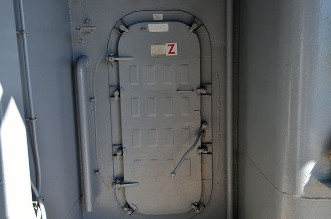